screw compressors
Piston compressors are used where high pressures (>20 bar) and relatively low volumes (<10,000 m3 h−1) are needed, but are mechanically relatively complex with many moving parts. Many applications require only medium pressure (<10 bar) and medium flows (around 10,000 m3 h−1). For these applications, rotary compressors have the advantage of simplicity, with fewer moving parts rotating at a constant speed, and a steady delivery of air without pressure pulses.
One rotary compressor, known as the dry rotary screw compressor, is shown in Figure 3.8 and consists of two intermeshing rotating screws with minimal (around 0.05 mm) clearance. As the screws rotate, air is drawn into the housing, trapped between the screws and carried along to the discharge port, where it is delivered in a constant pulse-free stream.
Screws in this compressor can be synchronized by external timing gears. Alternatively one screw can be driven, the second screw rotated by contact with the drive screw. This approach requires oil lubrication to be sprayed into the inlet air to reduce friction between screws, and is consequently known as a wet rotary screw compressor. Wet screw construction, though, obviously introduces oil contamination into the air which has to be removed by later oil separation units.
rotary compressors
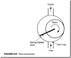
The vane compressor, shown in Figure 3.9, operates on similar principles to the hydraulic vane pump described in Chapter 2, although air compressors tend to be physically larger than hydraulic pumps. An unbalanced design is shown; bal- anced versions can also be constructed. Vanes can be forced out by springs or, more commonly, by centrifugal force.
A single-stage vane compressor can deliver air at up to 3 bar, a much lower pressure than that available with a screw or piston compressor. A two-stage vane compressor with large low-pressure and smaller high-pressure sections linked by an intercooler allows pressures up to 10 bar to be obtained.
Figure 3.10 shows a variation on the vane compressor called a liquid ring compressor. The device uses many vanes rotating inside an eccentric housing and contains a liquid (usually water) which is flung out by centrifugal force to form a liquid ring which follows the contour of the housing to give a seal with no leak- age and minimal friction. Rotational speed must be high (typically 3000 rpm) to create the ring. Delivery pressures are relatively low at around 5 bar.
The lobe compressor of Figure 3.11 (often called a Roots blower) is often used when a positive displacement compressor is needed with high delivery vol- ume but low pressure (typically 1–2 bar). Operating pressure is mainly limited by leakage between rotors and housing. To operate efficiently, clearances must be very small, and wear leads to a rapid fall in efficiency.
