Mounting arrangements
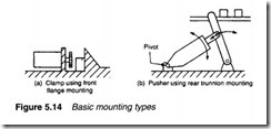
Cylinder mounting is determined by the application. Two basic types are shown in Figure 5.14. The clamp of Figure 5.14a requires a simple fixed mounting. The pusher of Figure 5.15b requires a cylinder mount which can pivot.
Figure 5.15 shows various mounting methods using these two basic types. The effects of side loads should be considered on non centreline mountings such as the foot mount. Swivel mounting obviously requires flexible pipes.
Cylinder dynamics
The cylinder in Figure 5.16a is used to lift a load of mass M. Assume it is retracted, and the top portion of the cylinder is pressurised. The extending force is given by the expression:
To lift the load at all, F>Mg+f where M is the mass and f the static frictional force.
The response of this simple system is shown in Figure 5.16b. At time W the rod side of the cylinder is vented and pressure is applied to the other side of the piston. The pressure on both sides of the piston changes exponentially, with falling pressure P2 changing slower than inlet pressure P1, because of the larger volume. At time X, extension force P1A is larger than P2a, but movement does not start until time Y when force, given by expression 5.6, exceeds mass and frictional force.
The load now accelerates with acceleration given by Newton’s law:
Where Fa= P1A- P2a- Mg- f.
It should be remembered that Fa is not constant, because both P1 and P2 will be changing. Eventually the load will reach a steady velocity, at time Z. This velocity is determined by maximum input flow rate or maximum outlet flow rate (whichever is lowest). Outlet pressure P2 is determined by back pressure from the outlet line to tank or atmosphere, and inlet pressure is given by the expression:
The time from W toY, before the cylinder starts to move, is called the ‘dead time’ or ‘response time’. It is determined primarily by the decay of pressure on the outlet side, and can be reduced by de pressurising the outlet side in advance or (for pneumatic systems) by the use of quick exhaust valves (described in Chapter 4).
The acceleration is determined primarily by the inlet pressure and the area of the inlet side of the piston (term P1A in expression 5.6). The area, however, interacts with the dead time – a larger area, say, gives increased acceleration but also increases cylinder volume and hence extends the time taken to vent fluid on the outlet side.


