TYPES OF FITTINGS AND CONNECTORS
Some type of connector or fitting must be provided to attach the lines to the compo nents of the system and to connect sections of line to each other. There are many dif ferent types of connectors and fittings provided for this purpose. The type of connector or fitting required for a specific system depends on several factors. One determining factor is the type of fluid line (pipe, tubing, or flexible hose) used in the system. Other determining factors are the type of fluid medium and maximum operat ing pressure of the system. Some of the most common types of fittings and connectors are described in the following sections.
Connectors for Pipes and Tubing
High-pressure pipe or tubing can also be used for hydraulic circuits. In these applica tions, special threading or fittings are required to connect circuit components·.
Threaded Connectors
There are several different types of threaded connectors. In the type discussed in this section, both the connector and the end of the fluid line are threaded. These connec tors are used in some low-pressure fluid power systems, are usually made of steel, copper, or brass, and are available in a variety of designs.
Threaded connectors (Figure 8-9) are made with standard pipe threads cut on the inside surface (female). The end of the pipe is threaded with outside threads (male). Standard pipe threads are tapered slightly to ensure tight connections. The amount of taper is approximately 3/4 inch in diameter per foot of thread.
Metal is removed when pipe is threaded, thinning the pipe and exposing new and rough surfaces. Corrosion agents work more quickly at such points than elsewhere. If pipes are assembled with no protective compounds on the threads, corrosion sets in at once and the two sections stick together so that the threads seize when disassembly is attempted. The result is damaged threads and pipes. To prevent seizing, a suitable pipe thread compound is sometimes applied to the threads. The two end threads must be kept free of compound so that it will not contaminate the hydraulic fluid. Pipe com pound, when improperly applied, may get inside the lines and damage pumps, control equipment, and other components of the system.
Another material used on pipe threads is sealant tape. This tape, which is made of Teflon, provides an effective means of sealing pipe connections and eliminates the necessity of torquing connections to excessively high values in order to prevent leaks. It also provides for ease of maintenance whenever it is necessary to disconnect pipe joints. The tape is applied over the male threads, leaving the first thread exposed. After the tape is pressed firmly against the threads, the joint is connected.
Flanged Connectors
Bolted flange connectors (Figure 8-10) are suitable for most pressures now in use. The flanges are attached to the piping by welding, brazing, or tapered threads, or by rolling and bending into recesses. Those illustrated are the most common types of flange joints used. The same types of standard fitting shapes-tee, cross, elbow, and so forth-are manufactured for flange joints. Suitable gasket material must be used between the flanges.
Welded Connectors
Welded joints connect the subassemblies of some fluid power systems, especially in high-pressure systems that use pipe for fluid lines. The welding is done according to standard specifications that define the materials and techniques.
Brazed Connectors
Silver-brazed connectors are commonly used for joining nonferrous piping in the pressure and temperature range where their use is practical. Use of this type of con nector is limited to installations in which the piping temperature will not exceed 425″F and the pressure in cold lines will not exceed 3,000 psi. Heating the joint with an oxyacetylene torch melts the alloy. This causes the alloy insert to melt and fill the few thousandths of an inch of annular space between the pipe and fitting.
Flared Connectors
Flared connectors are commonly used in fluid power systems containing lines made of tubing. These connectors provide safe, strong, dependable connections without the need for threading, welding, or soldering the tubing. The connector consists of a fit ting, a sleeve, and a nut (Figure 8-11).
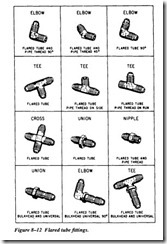
The fittings are made of steel, aluminum alloy, or bronze. The fitting used in a connec tion should be made of the same material as the sleeve, the nut, and the tubing. For example, use steel connectors with steel tubing and aluminum alloy connectors with aluminum alloy tubing. Fittings are made in union, 45-degree and 90-degree elbows, tee, and various other shapes (Figure 8-12).
Tees, crosses, and elbows are self-explanatory. Universal and bulkhead fittings can be mounted solidly with one outlet of the fitting extending through a bulkhead and the other outlet(s) positioned at any angle. Universal means the fitting can assume the angle required for the specific installation. Bulkhead means the fitting is long enough to pass through a bulkhead and is designed so it can be secured solidly to the bulkhead.
For connecting to tubing, the ends of the fittings are threaded with straight machine threads to correspond with the female threads of the nut. In some cases, however, one end of the fitting may be threaded with tapered pipe threads to fit threaded ports in
pumps, valves, and other components. Several of these thread combinations are shown in Figure 8-12.
Tubing used with flare connectors must be flared prior to assembly. The nut fits over the sleeve and when tightened, it draws the sleeve and tubing flare tightly against the male fitting to form a positive seal.
The male fitting has a cone-shaped surface with the same angle as the inside of the flare. The sleeve supports the tube so vibration does not concentrate at the edge of the flare and distributes the shearing action over a wider area for added strength.
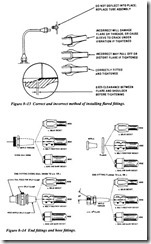
Correct and incorrect methods of installing flared-tube connectors are illustrated in Figure 8-13. Tubing nuts should be tightened with a torque wrench to the values spec ified in applicable technical publications.
If an aluminum alloy flared connector leaks after being tightened to the required torque, it must not be tightened further. Overtightening may severely damage or com pletely cut off the tubing flare, or may result in damage to the sleeve or nut. The leak ing connection must be disassembled and the fault corrected.
If a steel tube connection leaks, it may be tightened 1/16 tum beyond the specified torque in an attempt to stop the leakage. If the connection continues to leak, it must be disassembled and the problem corrected.
Connectors for Flexible Hose
There are various types of end fittings for both the piping connection side and the hose connection side of hose fittings. Figure 8-14 shows commonly used fittings.
The piping side of an end fitting comes with several connecting variations: flange, JIC 37″ flare, 0-ring union, and split clamp, to name a few. Not all varieties are available for each hose.


