CONTROL VALVES
It is impossible to design a practical fluid power system without some means of control ling the volume and pressure of the fluid, and directing that flow to the proper operating units. This is accomplished by the inclusion of control valves in the hydraulic circuit.
A valve is defined as any device by which the flow of fluid may be started, stopped, regulated, or directed by a movable part that opens or obstructs passage of the fluid. Valves must be able to accurately control fluid flow and system pressure, and to sequence the operation of all actuators within a hydraulic system.
Hydraulic control values can utilize a variety of actuators that activate their function. Nor mally these actuators use manual, electrical, mechanical, or pneumatic power sources.
VALVE CLASSIFICATIONS
Valves are classified by their intended use: flow control, pressure control, and direction control. Some valves have multiple functions that fall into more than one classification.
Flow Control Valves
Flow control valves are used to regulate the flow of fluids. Control of flow in hydrau lic systems is critical because the rate of movement of fluid-powered machines or actuators depends on the rate of flow of the pressurized fluid. Some of the major types of flow control valves include:
Ball Valves
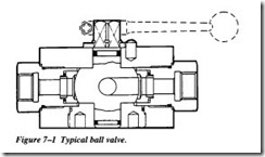
Ball valves are shutoff valves that use a ball to stop or start the flow of fluid down stream of the valve. The ball, shown in Figure 7-1, performs the same function as the disc in other valves. As the valve handle is turned to open the valve, the ball rotates to a point where part or the entire hole that is machined through the ball is in line with the valve body inlet and outlet. This allows fluid flow to pass through the valve. When the ball is rotated so that the hole is perpendicular to the flow path, the flow stops.
Most ball valves are the quick-acting type. They require a 90-degree turn ofthe actua tor lever to either fully open or completely close the valve. This feature, coupled with the turbulent flow generated when the ball opening is partially open, limits the use of ball valves as a flow control device. This type of valve is normally limited to strictly an “on–of’ control function.
Gate Valves
Gate valves are used when a straight-line flow of fluid and minimum flow restriction are needed. Gate valves use a sliding plate within the valve body to stop, limit, or per mit full flow of fluids through the valve. The gate is usually wedge-shaped. When the valve is wide open, the gate is fully drawn into the valve bonnet. This leaves the flow passage through the valve fully open with no flow restrictions. Therefore, there is lit tle or no pressure drop or flow restriction through the valve.
Gate valves are not suitable for throttling volume. The control of flow is difficult because of the valve’s design and the flow of fluid slapping against a partially open gate can cause extensive damage to the valve. Except as specifically authorized by the manufacturer, gate valves should not be used for throttling.
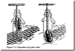
Gate valves are classified as either rising-stem or non-rising-stem valves. The non rising-stem valve is shown in Figure 7-2. The stem is threaded into the gate. As the handwheel on the stem is rotated, the gate travels up or down the stem on the threads while the stem remains vertically stationary. This type of valve will almost always
have a pointer indicator threaded onto the upper end of the stem to indicate the posi tion of the gate.
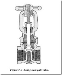
Valves with rising stems (Figure 7-3), are used when it is important to know by imme diate inspection whether the valve is open or closed or when the threads exposed to the fluid could become damaged by fluid contamination. In this valve, the stem rises out of the valve bonnet when the valve is opened.


