Low pressure conveying – Part II
A number of other materials were conveyed though a similar pipeline and this is pre- sented in Figure 12.5 for reference. The materials were fed into the pipeline by the same low pressure bottom discharge blow tank. A blow tank was used because of this versa- tility in conveying such a very wide range of materials.
Alumina
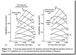
The conveying characteristics for two grades of alumina are presented in Figure 12.6. The mean particle size for the calcined alumina was about 66 f.Lm and that for the hydrate of alumina was about 60 f.Lm. The mean particle size of the iron powder was between these two and was capable of dense phase conveying. Alumina generally needs to have a smaller mean particle size before it is capable of being conveyed in dense phase. The two grades shown in Figure 12.6 do not have sufficient air retention for them to be capable of being conveyed in dense phase in a conventional conveying system, even with a high air supply pressure.
The particle density for the calcined alumina was about 3920 kg/m3 and that for the hydrate of alumina was about 2400 kg/m3. There is, in fact, remarkably little differ- ence in the conveying characteristics between these two materials. Only at the lowest air flow rates is there any significant difference and this is because the slope of the
constant pressure lines reduces with reduction in air flow rate. This is a feature of the conveying characteristics of a number of the materials presented here and will be considered further.
PVC powder
Conveying characteristics for PVC (polyvinylchloride) powder are presented in Figure 12.7a. This material had a mean particle size of about 90 f.Lm, which is significantly higher than that of either of the alumina materials above, but as will be seen in the section on high pressure conveying data, has dense phase conveying capability. From Figure 12.7a it will be seen that at low values of air flow rate the slope of the constant pressure drop lines change in a similar manner to those for the hydrate of alumina in Figure 12.6b. Since the PVC powder can be conveyed with much lower air flow rate, when a higher pressure gradient is available, it will be seen how the lines of constant pressure drop develop.
Barytes
Conveying characteristics for barytes are presented in Figure 12.7b. Barytes is a mater- ial that is widely used as a drilling mud powder, mainly because it has a particle dens- ity of about 4250 kg/m3. The material conveyed had a mean particle size of about 12 f.Lm and its bulk density was 1590 kg/m3. Almost any material having as low a mean particle size as this, regardless of its density, is generally capable of being conveyed in dense phase. This was demonstrated for barytes in the previous chapter with Figure
11.15 illustrating pressure gradient data for horizontal pipelines, and Figure 11.16 showing pressure drop data for 90° bends. With the low pressure gradient available for pipeline no. 2 the conveying of the barytes was limited to dilute phase.
Coal
Conveying characteristics for coal conveyed through the pipeline shown in Figure 12.5 are presented in Figure 12.8. A different grade of coal was conveyed through this pipeline. This had a top size of 25 mm, but still conveyed perfectly well through the 53 mm bore
pipeline with bends having a bend diameter, D, to pipe bore, d, ratio of 5:1. A conveying limit has been clearly identified on this set of conveying characteristics and corresponds to a conveying line inlet air velocity of about 12 m/s for this coal, with conveying line pressure drop values above about 0.2 bar, since the coal had a high proportion of fine material. A ‘no go area’ has also been clearly defined in which the pipeline will block if conveying is attempted in this area.
Fluidized bed combustor ash
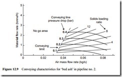
Similar data for a fluidized bed combustor ash is presented in Figure 12.9. ‘Bed ash’ comes in a wide range of particle sizes and for this material it was about 1.2 mm. A par- ticular feature of the material was that it was exceptionally abrasive.
The minimum conveying air velocity for the material was similar to that of the coal at about 12 m/s and, like the coal, contained a high proportion of ‘fines’. This is another material for which the slope of the constant pressure lines reduces with lower air flow rates and consequently the conveying performance compared with coal is very much poorer.
Pulverized fuel ash
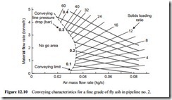
Conveying characteristics for another grade of fly ash conveyed through the pipeline shown in Figure 12.5 are presented in Figure 12.10. For dilute phase conveying the minimum conveying air velocity is about 11 m/s, but since the material conveys so well the transition to low velocity dense phase conveying is occurring and as a consequence the material is conveyed at a solids loading ratio of about 60 and with a corresponding conveying line inlet air velocity of about 6 m/s. Although these are all coal and ash products, Figures 12.8–12.10 do illustrate the wide range of conveying conditions that can be obtained with materials conveyed with low values of pressure gradient.


