Rotary valves
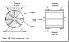
The rotary valve is probably the most commonly used device for feeding material into pipelines. This type of feeder consists of a bladed rotor working in a fixed housing. In many applications in which it is used its primary function is as an airlock, and so is often referred to as a rotary air lock. This basic type of valve is generally suitable for free flowing materials.
Drop-through valve
The type of valve described above is usually referred to as a ‘drop-through’ feeder and is depicted in Figure 3.4. This type of feeder is generally suitable for free flowing mate- rials. Material from the supply hopper continuously fills the rotor pockets at the inlet port which is situated above the rotor. It is then transferred by the motor-driven rotor to the outlet where it is discharged and entrained into the conveying line.
Valve wear
By the nature of the feeding mechanism, rotary valves are more suited to relatively non- abrasive materials. This is particularly the case where they are used to feed materials into positive pressure conveying systems. By virtue of the pressure difference across the valve, and the need to maintain a rotor tip clearance, air will leak across the valve. Wear, therefore, will not only occur by conventional abrasive mechanisms, but by erosive wear also. The problem of erosive wear can be a particularly serious one in pneumatic conveying and so Chapter 23 is entirely devoted to the subject.
Air leakage through the blade tip clearances, as a consequence of the pressure difference, can generate high velocity flows. This high velocity air flow will entrain fine particles, and the resulting erosive wear can be far more serious than the abrasive wear. Wear resistant materials can be used in the construction of rotary valves, and removable lining plates can be incorporated to help with maintenance, but wear can only be minimized, it cannot be eliminated if an abrasive material is to be handled.
For vacuum conveying duties there is no pressure drop across the valve when feeding, and so with no air leakage there is no erosive wear, only abrasive wear. This is only the situation when a rotary valve is used to feed a pipeline for a vacuum conveying system. If a rotary valve is used to off-load material from a hopper in a vacuum conveying system the situation is effectively the same as described above for feeding a positive pressure system. In this case the leakage air will additionally by-pass the conveying system by being drawn directly into the exhauster, and so starve the conveying pipeline of air. This point is considered further below.
By the same reasoning there will be no air leakage, and hence no erosive wear, with a rotary valve when used for off-loading material from a reception hopper on a positive pressure conveying system.
Alternative designs
As the rotary valve is probably the most common feeding device in use, it is not surprising that much effort has gone into to developing it further. The improvement in materials and construction methods to make it more acceptable for handling abrasive materials is one such area. The reduction in air leakage and the development of a rotary valve capable of operating at much higher pressures, and across much higher pressure differentials, has been another. Its capability for handling a wider range of materials was an early development.
Off-set valve
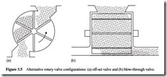
Rotary valves that have an off-set inlet for material feed are often employed in applications where shearing of the material should be avoided. A sketch of such a valve is given in Figure 3.5. They employ a side inlet, generally with an adjustable flow control, so that the angle of flow of the material does not permit it to fill the rotor pocket. As the rotor rotates toward the housing, material flows into the trough of the rotor and so pre- vents shearing. This type of valve is widely used for feeding pelletized materials.
Blow-through valve
Another variation of the standard type of feeder is the ‘blow-through’ valve, which is also shown in Figure 3.5. Here the conveying air passes through and purges the dis- charging pockets such that the material entrainment into the conveying pipeline actually takes place in the valve itself. These valves are primarily intended for use with the more cohesive types of material, since these materials may not be discharged satisfactorily when presented to the outlet port of a ‘drop-through’ valve.

