Pipeline purging
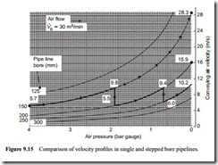
In many applications it is necessary to purge the pipeline clear of material at the end of a conveying run, particularly with perishable commodities and time limited products. In single bore pipelines this is rarely a problem, even if the material is conveyed in dense phase, because the velocity at the end of the pipeline is usually sufficiently high. There can, however, be problems with stepped pipelines. A comparison of the velocity profiles for flow in single and stepped bore pipelines is presented in Figure 9.15.
This is drawn for an air flow rate of 30 m3/min at free air conditions. It relates to the dense phase conveying of a material for which the minimum conveying air velocity is about 5 m/s. This is similar to the plot shown in Figure 9.12, except that the air flow is presented from left to right with the new figure. Although this may be more conventional in terms of system sketching, it does mean that the air pressure axis is reversed, and is offered simply as an alternative means of presentation.
Figure 9.15 is developed further in Figure 9.16 with empty conveying line velocity profiles added. This also provides a comparison between single bore and stepped bore pipelines, with respect to purging, and illustrates the problem towards the end of a stepped pipeline.
At the end of a conveying run, with no material to convey, the pressure at the material feed point, at the start of the pipeline, will drop to that of the air only pressure drop value. For low velocity dense phase conveying the empty line pressure drop will only be a fraction of the pressure drop required for conveying. Thus the velocity of the air through a single bore empty pipeline will be very high throughout the entire length of the pipeline. At the end of the pipeline the air velocity will be exactly the same as in the conveying case, because the pressure here is always atmospheric.
At the material feed point the air velocity will only be slightly lower than that at the exit since the air pressure at the feed point is so much lower when material is not being conveyed. This will be seen with reference to Equation (9.11), for the air pressure, p,
is in the denominato.r of the equation and there will be no significant change in the volumetric flow rate, V0, with reduction in pressure.
With the stepped bore pipeline this same volumetric flow rate of air has to expand into the larger bore section of pipeline, and so its velocity will reduce, as shown in Figure 9.16. At the end of the pipeline the situation is exactly the same as in the single bore pipeline case. The velocity for both conveying and purging will be the same, because the pressure here is always atmospheric. Since the purging velocity will not be constant throughout the pipeline the potential for clearing material from the latter sections of stepped pipelines by purging, therefore, will be severely limited.
