Vacuum pumps
Theory
Mechanical vacuum pumps can be looked on as special kinds of compressors and so the theoretical analysis of their behaviour is based on the same principles. A vacuum pump is a compressor in which the inlet pressure is that of the chamber to be evacuated and the delivery pressure is that of the atmosphere (at least in those pumps which are designed to evacuate air back to the atmosphere).
The analysis of compressor behaviour as described in earlier chapters should be referred to for background information on the theory. There are several vacuum regimes that can be studied. One of the common situations is where the pump is used to evacuate a chamber which is initially at atmospheric pressure, reducing gradually until the final depression is reached. It will be apparent that, in a pump which can generate a depression of 0.01 torr, the effective compression ratio varies from unity to 76 000. It would be impossible to attain optimum efficiency over such a range, so the design of vacuum pumps is usually a compromise.
The characteristics of the vacuum circuit can affect considerably the behaviour and efficiency of the pump and, when designing an installation, equal weight should be given to the system as to the pump.
Units
Vacuum pressure is quoted in torr (I torr= l mm Hg) or in kPa. Alternatively, depression is quoted as a percentage of atmospheric pressure, in which case the percentage is numerically equal to the vacuum pressure in kPa. Thus 85% vacuum is equal to a pressure of -85 kPa.
The quantity of a gas in a partial vacuum is expressed as a product of pressure and volume (commonly called PV units) because this is a measure of the total number of molecules in a given volume. A variety ofPV units are in use: torr litres is the traditional unit; micron litres (ie micrometres of Hg) is also used; in SI units, the preference is for Newton metres (I torr litre= 0.1333 N m).
Leakage rate is often expressed as torr litre/s, !usee (micron litre/s), clusec (O.Ollusec) or in SI units N rn/s.
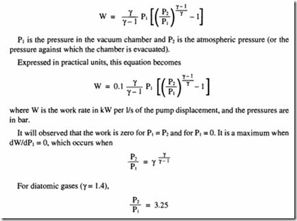
If the vacuum required is lower than is represented by this value of pressure ratio, the work increases to a maximum and then decreases; the drive to the pump must be capable of supplying this maximum.
Withy= 1.4, the maximum value for the work rate is 0.043 kW per 1/s of pump flow.
Conductance
An important concept in vacuum technology is that of conductance in a pipe or an aperture. It is usually given the symbol U and is defined as:
flow of gas in PV units pressure difference across the device The units are litre/s.
For the determination of conductance in various types of flow restriction, reference should be made to specialist texts, but two of the most common restrictions are long pipes and apertures, for which the following approximations may be used. For a long pipe of constant diameter and air at 25°C,
