COMPRESSOR LUBRICATION
Lubrication is an extremely important parameter in compressor performance, its function being to dissipate frictional heat, reduce wear on sliding surfaces, reduce internal leakage and protect parts from corrosion. The lubricant can also act to flush away wear products, contaminants in the air and moisture. There is a tendency with modern compressors to dispense with oil in the compression chamber so as to avoid having to separate out the oil carried over with the air into the supply passage. This serves to remove the risk of contamination at source, which is so important for air needed for processing (food preparation, for example). Lubrication of the moving parts away from the chamber is usually necessary.
The choice of lubricating system and the lubricant itself are important, particularly as lubrication requirements differ with different types of compressor and in the case of reciprocating compressors in different sections of the machine.
Most modern compressors, whether reciprocating or rotary rely on pressure, rather than splash lubrication (except for small single cylinder units). There is seldom any problem provided that the manufacturer’s recommendations regarding the type of lubricant, the setting of the pressure relief valve on the pump and the maintenance schedules for oil and filter changes are observed.
Lubrication systems
Experience has shown that certain lubrication systems are best for specific types of compressors, although alternative choices are normally available to the designer. The most common systems are:
• splash lubrication
• flood lubrication (gravity)
• force feed lubrication
• injection lubrication
Reciprocating compressors
In these compressors, the simplest arrangement is splash lubrication, shown in Figure I, whereby a projection on the connecting rod dips into oil held in the crankcase, which acts as an oil reservoir and rnust be closed with the exception of a small breather hole. Lubricant is dispersed, mainly in the form of an oil mist reaching the bearings, sliding surfaces and cylinders. For best control the splash oil should be taken from a trough, or failing that some
provision must be made to keep the crankcase oil at a constant level. Water which collects at the bottom of the crankcase should be drawn off at the intervals specified by the manufacturer, either manually or automatically.
Splash lubrication is largely limited to small single-acting reciprocating compressors.
It has a number of disadvantages:
• the lubricant cannot be filtered and its life is limited,
• lubrication at start up may be marginal,
• the bearing film is thin and is not supplied under pressure,
• the level of oil cannot be guaranteed unless strict maintenance schedules are observed and the compressor kept level.
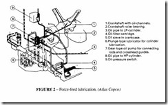
Flood lubrication is widely used on horizontal compressors for lubricating the bearings and crosshead. The oil flow is under the pressure of gravity after first being elevated by a disc, oil ring, chain or collar on the crankshaft which lifts it to a trough with distribution tubes or to the upper part of the journals (see Figure 2). This provides better control of the oil flow but the pressure is low and not generally considered sufficient for modern high speed compressors.
Force feed lubrication utilizing a circulatory system is normally to be preferred; this is similar to automobile engine lubrication. Feed is taken from an oil reservoir by a plunger or gear pump. Actual circulation may be by gravity when the oil is pumped to an overhead reservoir, or may be fed directly from the pump under pressure through pipes to the various lubrication points. Oil pressure is maintained constant by a spring loaded overflow valve. For cylinder lubrication of crosshead compressors, piston type lubricators are normally used.
Sight-feed drip oilers are occasionally used to lubricate small parts. These are similar
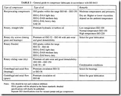
!SO-L grades will be adopted as the future standards; detailed specifications will shortly be published.
Separate ISO classifications exist for vacuum pumps and gas compressors.
good condition. Siphon wick oilers may be used when it is important that there should be no undue variation in oil level in the container. Grease lubrication may be provided at certain points (eg to lubricate rolling bearings). In this case the lubricating points are either fitted with grease nipples or screw-down oil cups.
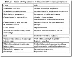
In the case of cylinders, the ideal oil feed is that which will provide efficient and effective lubrication with a minimum amount of oil and at the same time maintain a good piston seal- an excess of oil is undesirable because it then has to be removed. A practical check is to service the discharge valves periodically and examine their appearance. They should not be dry nor show signs of rust (insufficient oil) or be excessively wet (excess of oil). They should have a wet appearance and be oily to the touch. Excess of oil can also be noted by the appearance of pools of oil lying in the cylinders or surplus oil on the connecting rods.
Figure 2 shows the various lubrication flows for a typical reciprocating compressor.
This is for a compressor supplying industrial air in which a small amount of oil is acceptable, so the cylinders are lubricated. If oil-free air were required, the cylinder lubrication would be omitted, but crankcase lubrication would remain. It is customary to incorporate an externally mounted gear pump with a pressure relief valve which controls the pressure to the moving parts. Oil is drawn into the pump through a submerged oil strainer and from the pump passes through a pressure filter with a disposable element. Oil is fed to the main bearings, through the connecting rods to the small-end bearings and crosshead and drains back into the crankcase.
In this design, the cylinders are lubricated by a crankshaft-driven force feed lubricator drawing oil from a separate reservoir. The valves seldom require separate lubrication.
Vane compressors
Two kinds of vane compressors are available, oil-free and oil-flooded. In the former kind, adequate lubrication is necessary to minimize friction and wear on the vanes and/or wear ring, and to assist in sealing. Quite high bearing pressures can be generated by the force of the vanes on the slots, calling for a lubricant forming a tenacious oil film.
Bearing lubrication is normally independent by means of a force-feed lubricator. Oil for lubricating the vanes may be fed to the casing via the air intake, direct to the casing or through the shaft. The first method is usually preferred, loading the air with oil from an atomizer; air at discharge pressure may be used to inject oil into the intake. The other two methods involve force feeding, either direct to the ends of the rotor or through a hole in the centre of the shaft. In the latter case, interconnecting radial holes drilled along the length of the shaft throw out oil under centrifugal force. The vanes in these compressors are usually made from cast iron which has good self-lubricating properties.
In the second kind of vane compressor, the compression chamber is flooded with oil, for the purpose of removing the heat of compression. Much more oil is supplied than is needed for lubrication or for sealing. Vanes in this type of compressor are usually made of a reinforced resin material, and are much lighter than metallic vanes, reducing the centrifugal bearing forces.
Rotary compressors of the dry type do not require in ternallubrication because the rotors operate with a positive clearance. Only shaft bearings and the timing gears require lubrication; plain bearings may be lubricated by ring oilers and timing gears by splash lubrication. When rolling bearings are used, bearings at the timing end may be lubricated by oil and those at the other end by grease.
Oil-flooded rotary compressors (vane or screw)
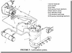
Rotary compressors require lubrication of the bearings, the step-up gears and the timing gears where fitted (although in most rotary screw compressors, the screws drive each other and no timing gears are necessary). The oil-flooded types use the same oil for both lubrication and cooling injected into the compression chamber. Usually the oil is circulated by an externally mounted gear pump, drawing oil from the oil separator. The oil in the separator is at supply pressure, which is high enough in itself to circulate the oil without a pump. Some manufacturers dispense with a pump and rely solely on pressure circulation. This is bound to be a compromise for two reasons: at start-up, when the pressure is low the circulation flow is lower than desirable; and at varying speeds the oil flow is constant rather than proportional to speed. For mobile units this seems to work well, but industrial units usually include a pump. Where the pump is driven off the main drive, circulation stops when the rotors stop. But where the circulation is done by pressure alone, oil flow would persist as long as air pressure was present in the reclaimer, with the result that oil would be discharged back into the compression space. This is clearly undesirable so this kind of pumpless circulation has to have a non-return oil-stop valve to prevent it; such a valve is pilot operated from a pressure signal in the delivery casing.
The oil separator is one of the critical items in an oil flooded type of compressor. Its operation is shown in Figure 4. The method of separation is partly through mechanical impingement and partly through agglomeration in the filter pack.
Turbocompressors
In a turbocompressor only the bearings and gears require lubrication. The duty is less severe than for a positive displacement rotary compressor. The oil system may include an immersion heater as well as a cooler to maintain a stable oil temperature.
Compressor fires
One problem which sometimes occurs both in reciprocating and in oil-flooded units is the occurrence of internal fires and explosions. This phenomenon is not fully understood, but appears to be associated either with the use of an incorrect oil, running with a low oil level or not keeping strictly to the correct maintenance procedure. The presence of rust, aluminium or magnesium in the system can contribute to the danger. Combustion can start in the reclaimer vessel of a flooded unit where the oil is present in a finely divided form. The build-up of carbon deposits appears to serve as a starting point for fires. Regular cleaning and strict attention to manufacturer’s recommendations will usually prevent this problem. BS 6244 should be studied for guidance on safety and includes information on avoiding the potential for fires.
Synthetic lubricants
There has been much interest in recent years in the use of synthetic fire resistant lubricants based on phosphate ester, di-ester, glycol or silicone, which are used on their own or blended with mineral oils. They reduce the combustible mists and minimize carbonaceous residues on valves and piping; they are claimed to have a longer life and superior lubricating properties. One should be wary of changing to the use of such lubricants without reference to the compressor manufacturer, and certainly one should never attempt to mix them with each other or with conventional mineral oils, despite any claim that the two are compatible.
For high output reciprocating compressors, dibasic ester fluids are recommended; for refrigeration compressors, alkyl benzenes are used, and for rotary compressors poly alpha-olefines (PAO) are preferred.
Some of the problems that may arise are
• Incompatibility with metaiiic components.
• Incompatibility with the elastomers used in the diaphragms or seals.
• Plastics used in sight glasses or separator bowls may be affected.
• Paint used to coat the inside of pressure vessels or delivery passages may be softened and flake away, causing blockage of the filters.
• The cost wiii probably be higher (up to five times) than that of mineral oils.
• The lubrication properties may not be as good in the presence of water.
• The change periods may be shorter (although some suppliers claim an extended life).
• They tend to be more toxic, so precautions should be taken where the air is dis charged into working areas.
However they appear to be a good answer to the problem of fire hazards, and should be considered where this is a problem.
Safety aspects of compressor lubricants
Observation of the foiiowing guidelines should guarantee safe use of compressor lubri cants:
• Always use the oils recommended by the manufacturer.
• Never attempt to compensate for wear by the use of higher viscosity oil.
• Change ail filters at recommended times. If solid particles are present in the filter element, locate their source. Rust or finely divided metal particles can lead to fires.
• If there is suspicion of inadequate lubrication, the tissue paper test can be used. Wipe the surface of the internal parts with a thin piece of tissue paper; it should be evenly stained, not soaked or dry (suitable for non-oil-flooded machines only).
• Keep records of amount of lubricant used and try to identify exceptional consump tion.
• Ensure regular cleaning of oil and sludge from separators, reservoirs, aftercoolers and intercoolers.
• Never clean the inside of compressors with paraffin (kerosene) or carbon tetrachlo
ride.
• An open flame should never be used to inspect the interior of a compressor or pressure vessel.
• If overheating is suspected, aiiow the unit to cool weii below the spontaneous ignition temperature of the oil vapour (about 3l5°C).


