Material compatibility
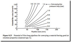
The different conveying performances for the two materials with respect to both conveying distance and pipeline bore illustrate the problems to be encountered when a pipeline or conveying system has to be used for the conveying of more than one mater- ial. Totally different flow rates must be expected when different materials are conveyed through the same pipeline, even if the conveying line pressure drop is the same. The parameter that this last group of curves does not show is that of the conveying air requirements, although it was shown clearly in Figures 8.2–8.4.
If more than one material has to be conveyed through a given pipeline, the air sup- ply has to be sufficient, in terms of volumetric capability, to convey the material with the requirement for the highest value of minimum conveying air velocity. When con- veying other materials, however, the volumetric flow rate may need to be reduced, otherwise the conveying potential may also be reduced.
This effect can be illustrated by reference to Figure 8.2. If 0.38 kg/s of air is used to convey material type B, a flow rate of about 7 tonne/h could be expected in a 200 m long pipeline of 75 mm bore with a conveying line pressure drop of 3 bar. If this same air flow rate was to be used with material type A, a material flow rate of about 15 tonne/h would be obtained. If the air flow rate was to be reduced to 0.10 kg/s for material type A, how- ever, a material flow rate of about 28 tonne/h could be expected in this same pipeline.
This aspect of system design is considered in detail in Chapter 19, together with similar influences of system design with respect to systems having multiple delivery points. Air requirements and consequent power requirements are also considered. This present chapter is concerned essentially with the performance of the pipeline. There will, of course, be problems with material feeding into these pipelines, and so the matching of the two will be taken into account in Chapter 19.
Design curves
One of the objects of this introductory chapter is to provide some basic data and information of the potential of pneumatic conveying systems for the conveying of various materials. As mentioned earlier, however, there are too many variables for a simple universal relationship to be applicable. Since only three variables can be represented on a single graph, a complete family of graphs is needed in order to represent a fourth variable. For this reason material type is considered as the fifth variable and only two material types are considered. This also necessarily means that only a limited number of incremental values of the fourth variable can be considered. To overcome this particular problem a sec- ond set of curves are presented in which the order of the first four variables are changed.
Conveying parameter combinations
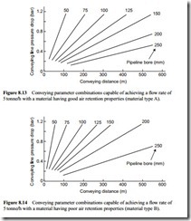
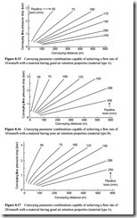
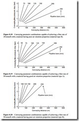
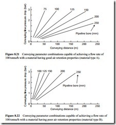
In the first set of curves conveying line pressure drop is plotted against conveying distance and lines of constant pipeline bore are superimposed. Material flow rate is rep- resented as the fourth variable in this set of curves and five values ranging from 5 to 100 tonne/h are considered. All five graphs are drawn for each material. The 10 graphs are presented in Figures 8.13–8.22.
With only 5 tonne/h being considered in Figures 8.13 and 8.14 the conveying line pressure drop was limited to 1.2 bar. This is extended to 3 bar for the other figures in this group.
With an increase to 20 tonne/h the 50 mm bore pipeline is no longer an option for the type B material.
With an increase to 50 tonne/h the 75 mm bore pipeline is no longer an option for the type B material.
With an increase to 100 tonne/h the conveying distance has been limited to 250 m because of the range of pipe bores and pressure drop values being considered.
With each one of these graphs being drawn for a given material flow rate, it will be seen that for any given conveying distance that a wide range of combinations of conveying line pressure drop and pipeline bore values are generally available that will satisfactorily meet the conveying requirement. If the conveying line pressure drop available for the system is limited, however, as it will be for a vacuum conveying system, the choice will be more restricted.
If there is no such limitation there is clearly a need to determine which of the pos- sible combinations are best for the given duty. Operating costs, and hence power
requirements are obviously the criterion for the basis of selection in this respect. This aspect of system selection is introduced in the next section of this chapter, in addition to being considered in detail in Chapter 11.
If a high pressure option is chosen, in order to achieve a high material flow rate in the smallest bore pipeline possible, over the range of air pressures being considered, consideration will have to be given to the conveying air expansion effects. High air supply pressures are often used for long distance conveying.
Over long distances, however, maximum values of solids loading ratio that can be achieved tend to be rather low, even for materials with very good air retention properties, as illustrated in Figure 8.5. As a consequence, conveying line inlet air velocities need to be quite high, and so with a high air supply pressure extremely high conveying line exit air velocities can result in a single bore pipeline.
If the material being conveyed is either abrasive or friable, such high conveying air velocities should be avoided. One means by which the general air velocity level can be lowered is to use a stepped pipeline. These are considered in relation to air flow rate evaluation in Chapter 9 and in a number of subsequent chapters with regard to the conveying of various materials.
Since the material has to be conveyed in suspension flow, however, conveying air velocities will still be relatively high. In this case the use of an alternative innovatory type of pneumatic conveying system would be worth considering, provided that one can be found to meet the required duty.
