logic elements
Many sequences are built around expressions such as:
‘If (W is present AND X is present AND Y is NOT present) OR Z is present then operate actuator Q’ (8.1) These are known as logic statements and are built around the three logic elements AND, OR, NOT. The logic symbols and operational tables for these three elements are shown in Figure 8.9. An AND gate thus gives an output pressure if, and only if, pressure is applied to both of its two inputs. The logic statement 8.1 above could thus be represented by Figure 8.10 which is, in effect, a piping diagram.
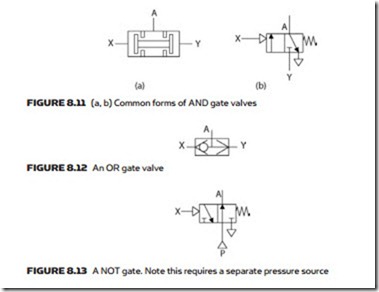
An AND gate can be constructed as in Figure 8.11a or b. In Figure 8.11a there is a movable unsprung spool which will shift left or right and block off a pressure signal which is applied on its own. If two pressures are applied simultaneously the spool will shift to allow the lowest pressure through and block the highest pressure. Figure 8.11a is often used as the symbol for an AND gate rather than the logic symbol in Figure 8.9.
The alternative AND gate of Figure 8.11b is a simple spring return valve where an output pressure is given if the spool has been shifted to the right AND a pressure is present at the base.
An OR gate can be constructed with a ball shuttle valve as in Figure 8.12. Again this symbol is often used on circuit diagrams instead of the earlier logic symbol of Figure 8.10. The element will pass the higher of the two input pressures.
A NOT gate (often called an inverter) is constructed with a spring return shuttle valve as in Figure 8.13. Note that, unlike the AND and OR gates, a NOT gate requires a separate pressure source.
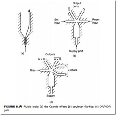
Logic devices (AND, OR gates and memories) can also be constructed us- ing the wall attachment or Coanda effect although these are relatively rare. The effect is based on the fact that a fluid stream exiting from a jet with a Reynolds number in excess of 1500 (giving very turbulent flow) tends to attach itself to a wall and remain there until disturbed as shown in Figure 8.14a.
This principle can be used to give a pneumatic set/reset (S–R) flip-flop memory in Figure 8.14b. If the set input is pulsed, the flow attaches itself to the right-hand wall, exiting via output Q. If the set input is then removed the Coanda effect keeps the flow on this route until the reset input is pulsed.
Figure 8.14c shows a fluidic OR/NOR gate. A small bias pressure keeps the signal on the right-hand wall, which causes it to exit via the right-hand port. If signal A or B is applied (at higher pressure than the bias) the flow switches over to the (A + B) output. When both A and B signals are removed, the bias pressure switches the flow back again.
tImers
Sequences often use time as part of the control. For example, a sequence could be: ‘Extend cylinder B, wait five seconds after limit b1 has made then extend cylinder C.’
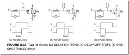
There are three types of timer, shown in Figure 8.15. Timer 8.15a is a DE- LAY-ON, commonly known as a TON. Timer 8.15b is a DELAY-OFF, commonly known as a TOF. Timer 18.15c is a ONE-SHOT or PULSE timer.
All use a similar principle with a small reservoir which is charged (or dis- charged) via an adjustable restriction which sets the time. The pressure in the
reservoir shifts the valve spool. Note the TOF timer requires a separate pressure supply.


