Batch conveying systems
The systems illustrated above have all been capable of continuous operation, conveying 24 h a day if required. In many processes, however, it may be more convenient to convey one batch at a time. If such a choice is possible it does mean that there will be a wider range of available system types from which to select. An additional classifica- tion of conveying systems, as indicated on Figure 2.1, is based on mode of operation. Conveying can either be carried out on a continuous basis or in isolated batches. If a reasonably steady flow of material is required, or a high flow rate, a continuous sequence of batches can be conveyed.
Although a batch conveying system may be chosen for a specific process need, the mode of conveying is, to a large extent, dictated by the choice of pipeline feeding device. The majority of batch conveying systems are based on blow tanks, and blow tanks are selected either because of their high pressure conveying capability, or because of the nature of the material fed into the pipeline. Single blow tank systems are often used for this type of conveying. Blow tanks as feeding devices are considered in detail in Chapters 3 and 4.
There are two main types of batch type conveying system to be considered. In one, the batch size is relatively large, and the material is fed into the pipeline gradually over
a period of time, and so can be considered as a semi-continuous system. In the other, the entire batch of material is fed into the pipeline as a single plug.
Semi-continuous systems
It should be noted that when batches of material are fed into the pipeline gradually, there is essentially no difference in the nature of the gas–solids flow in the pipeline with respect to the mode of conveying, at any given value of solids loading ratio. The blow tanks used vary in size from a fraction of a cubic metre to 20 m3 or more, generally depending upon the material flow rate required, and hence pipeline diameter, and a need to maintain a reasonable frequency of blow tank cycling. The material can be con- veyed in dilute or dense phase, depending upon the capability of the material, the pres- sure available and the conveying distance, as with continuously operating systems.
With a single blow tank it is not possible to utilize the pipeline, while the blow tank is being filled with material or when the system is being pressurized. Since batch convey- ing is discontinuous, steady state values of material flow rate, achieved during conveying, have to be higher than those for continuously operating systems in order to achieve the same time averaged mean value of material flow rate. This means that air requirements and pipeline sizes have to be based on the maximum, or steady state, conveying rate. The intermittent nature of the conveying cycle is illustrated in Figure 2.7.
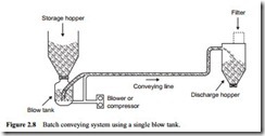
In comparison with a continuously operating system, therefore, the batch operating system would appear to be at a disadvantage. Blow tank systems, however, can operate at very much higher pressures to compensate, and they can be configured to operate continuously, as considered in Chapter 4 on high pressure pipeline feeding systems. With their very high pressure capability they can also be used in situations where material has to be fed into a process which is also at a high pressure. A typical batch conveying system based on a single blow tank is illustrated in Figure 2.8.
Single plug systems
In the single plug conveying system the material is effectively extruded into the pipeline as a single plug of material, typically about 10 m long. This plug of material is
then blown through the pipeline as a single plug. A certain amount of material will tail off the end of the plug as it is conveyed, but the front of the plug will sweep up material deposited in the pipeline by the previous plug. It therefore takes a few conveying cycles to ‘condition’ the pipeline before regular or steady conveying is achieved.
The material will be conveyed at a low velocity, in what may be regarded as dense phase, but solids loading ratios do not have the same significance here, and steady state conveying, as depicted in Figure 2.7, does not apply either. Regardless of this, com- panies do quote solids loading ratios for these systems, but they can be used as a basis of comparison between systems with regard to air requirements.
The air pressure has to overcome the frictional resistance of the plug of material in the pipeline. As a result blow tank sizes are rarely larger than 3 or 4 m3 unless very large diameter pipelines are employed. In terms of system design, a cycling frequency is selected to achieve the required material flow rate, which determines the batch size. The pipe diameter is then selected such that the frictional resistance of the plug results in a reasonable air supply pressure to propel the plug at the given velocity. A sketch of a typical single plug conveying system is given in Figure 2.9.
Single plug systems are capable of conveying a wide range of materials, and generally at much lower velocities than can be achieved in continuously operating systems. Many coarse, granular materials are either friable or abrasive and can only be conveyed in dilute phase with conventional conveying systems, and so single plug systems can represent a viable alternative. Material discharge often represents a problem with this type of system. Although the plugs of material are conveyed at a relatively low velocity, once they are discharged from the pipeline the high pressure air released behind the plug can cause severe erosion of the pipeline on venting.

