RESERVOIRS, STRAINERS, FILTERS, AND ACCUMULATORS
Fluid power systems must have a sufficient and continuous supply of uncontaminated fluid to operate efficiently. This chapter covers hydraulic reservoirs; various types of strainers and filters; and accumulators that are typically installed in fluid power systems.
RESERVOIRS
A hydraulic system must have a reserve of fluid in addition to that contained in the pumps, actuators, pipes, and other components of the system. This reserve fluid must be readily available to make up losses of fluid from the system, to make up for compression of fluid under pressure, and to compensate for the loss of volume as the fluid cools. This extra fluid is contained in a tank usually called a reservoir. A reservoir may sometimes be referred to as a sump tank, service tank, operating tank, supply tank, or base tank.
In addition to providing storage for the reserve fluid needed for the system, the reservoir acts as a radiator for dissipating heat from the fluid. It also acts as a settling tank where heavy particles of contamination may settle out of the fluid and remain harmlessly on the bottom until removed by cleaning or flushing the reservoir. Also, the res ervoir allows entrained air to separate from the fluid.
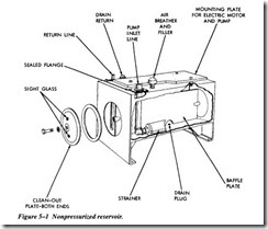
Most reservoirs have a capped opening for filling, an air vent, an oil level indicator or dip stick, a return line connection, a pump inlet or suction line connection, a drain line connection, and a drain plug. See Figure 5-1.
The inside of the reservoir generally will have baffles to prevent excessive sloshing of the fluid and to put a partition between the fluid return line and the pump suction or inlet line. The partition forces the returning fluid to travel farther around the tank before being drawn back into the active system through the pump inlet line. This aids in settling the contamination and separating air entrained in the fluid.
Large reservoirs are desirable for cooling. A large reservoir also reduces recirculation, which helps settle contamination and separates entrained air. As a rule of thumb, the ideal reservoir should be two to three times the pump outlet per minute. However, because of space limitations in mobile and aerospace systems, the benefits of a large reservoir may have to be sacrificed. But, they must be large enough to accommodate thermal expansion of the fluid and changes in fluid level due to system operation.
ACCUMULATORS
An accumulator is a pressure storage reservoir in which hydraulic fluid is stored under pressure from an external source. The storage of fluid under pressure serves several purposes in hydraulic systems.
In some hydraulic systems, it is necessary to maintain the system pressure within a specific pressure range for long periods oftime. It is very difficult to maintain a closed system without some leakage, either external or internal. Even a small leak can cause a decrease in pressure. By using an accumulator, leakage can be compensated for and the system pressure can be maintained within acceptable range for extended periods of time. Accumulators also compensate for thermal expansion and contraction of the liquid due to variations in temperature or generated heat.
A liquid flowing at a high velocity in a pipe will create a backward surge when stopped suddenly. This sudden stoppage causes an instantaneous pressure two to three times the operating pressure of the system. These pressures or shocks produce objectionable noise and vibrations, which can cause considerable damage to piping, fittings, and compo nents. The incorporation of an accumulator enables such shocks and surges to be absorbed or cushioned by the entrapped gas, thereby reducing their effects. The accu mulator also dampens pressure surges caused by pulsing delivery from the pump.
There are times when hydraulic systems require large volumes of liquid for short peri ods of time. This is due to either the operation of a large cylinder or the necessity of operating two or more circuits simultaneously. It is not economical to install a pump of such large capacity in the system for only intermittent usage, particularly if there is suf ficient time during the working cycle for an accumulator to store enough liquid to aid the pump during these peak demands. The energy stored in accumulators may be also used to actuate hydraulically operated units if normal hydraulic system failure occurs.
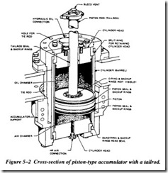
Piston-type accumulators consist of a cylindrical body, called a barrel, closures on each end, called heads, and an internal piston. The piston may be fitted with a tailrod, which extends through one end of the cylinder (Figure 5-2), or it may not have a tail rod at all. In the latter case, it is referred to as a floating piston. Hydraulic fluid is pumped into one end of the cylinder, and the piston is forced toward the opposite end
of the cylinder against a captive charge of air or an inert gas, such as nitrogen. Some times the amount of air charge is limited to the volume within the accumulator; other installations may use separate air flasks that are piped to the air side of the accumula tor. Piston accumulators may be mounted in any position.
The gas portion of the accumulator may be located on either side of the piston. The orientation and type of accumulator are based on such criteria as available space, mainte nance accessibility, size, need for external monitoring, contamination tolerance, seal life, and safety. The purpose of the piston seals is to keep the fluid and gas separate.
Usually, tailrod accumulators use two piston seals, one for the air side and one for the oil side, with the space between them vented to the atmosphere through a hole drilled the length of the tailrod. When the piston seals fail in this type of accumulator, air or oil leakage is apparent. However, seal failure in a floating piston or nonvented tailrod accumulators will not be as obvious. Therefore, more frequent attention to venting or draining the airside is necessary. An indication of worn and leaking seals can be detected by the presence of significant amounts of oil in the airside.
Bladder- Type Accumulators
Bladder- or bag-type accumulators consist of a shell or case with a flexible bladder inside the shell. See Figure 5-3.
The bladder is larger in diameter at the top (near the air valve) and gradually tapers to a smaller diameter at the bottom. The synthetic rubber is thinner at the top of the bladder than at the bottom. The operation of the accumulator is based on Barlow’s formula for
hoop stress, which states: “The stress in a circle is directly proportional to its diameter and wall thickness.” This means that for a certain thickness, a large-diameter circle will stretch faster than a small-diameter circle; or for a certain diameter, a thin-wall hoop will stretch faster than a thick-wall hoop. Thus, the bladder will stretch around the top at its largest diameter and thinnest wall thickness, and then will gradually stretch down ward and push itself outward against the walls of the shell. As a result, the bladder is capable of squeezing out all the liquid from the accumulator. Consequently, the bladder accumulator has a very high volumetric efficiency. In other words, this type of accumu lator is capable of supplying a large percentage of the stored fluid to do work.
The bladder is precharged with air or inert gas to a specified pressure. Fluid is then forced into the area around the bladder, further compressing the gas in the bladder. This type of accumulator has the advantage that as long as the bladder is intact there is no exposure of fluid to the gas charge and therefore less danger of an explosion.


