Process control valves and actuators
In most pneumatic process control schemes, the final actuator controls the flow of a fluid. Typical examples are liquid flow for chemical composition control, level control, fuel flow for temperature control and pressure control. In most cases the actual control device will be a pneumatically actuated flow control valve.
Even with totally electronic or computer-based process control schemes, most valves are pneumatically-operated. Although electrically-operated actuators are available, pneumatic devices tend to be cheaper, easier to maintain and have an inherent, and predictable, failure mode.
It is first useful to discuss the way in which fluid flow can be con trolled. It is, perhaps, worth noting that these devices give full pro portional control of fluid flow, and are not used to give a simple flow/no-flow control.
Flow control valves
All valves work by putting a variable restriction in the flow path. There are three basic types of flow control valves, shown in Figures
to 7.14. Ofthese the plug, or globe valve (Figure 7.12) is prob ably most common. This controls flow by varying the vertical plug position, which alters the size of the orifice between the tapered plug and valve seat. Normally the plug is guided and constrained from sideways movement by a cage, not shown in Fig. 7.12a for simplicity.
The valve characteristics define how the valve opening controls flow. The characteristics of the globe valve can be accurately pre determined by machining the taper of the plug. There are three common characteristics, shown in Figure 7.12b. These are specified for a constant pressure drop across the valve, a condition which rarely occurs in practical plants. In a given installation, the flow through a valve for a given opening depends not only on the valve, but also on pressure drops from all the other items and the piping in the rest of the system. The valve characteristic (quick opening, linear, or equal percentage) is therefore chosen to give an approxi-
mately linear flow/valve position relationship for this particular configuration.
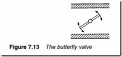
A butterfly valve, shown in Figure 7.13, consists of a large disc which is rotated inside the pipe, the angle determining the restriction. Butterfly valves can be made to any size and are widely used for control of gas flow. They do, however, suffer from rather high leakage in the shut-off position and suffer badly from dynamic torque effects, a topic discussed later.
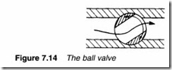
The ball valve, shown in Figure 7.14, uses a ball with a through hole which is rotated inside a machined seat. Ball valves have an excellent shut-off characteristic with leakage almost as good as an on/off isolation valve.
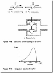
When fluid flows through a valve, dynamic forces act on the actuator shaft. In Figure 7.15a, the flow assists opening (and opposes the closing) of the valve. In Figure 7.5b, the flow assists the closing (and opposes the opening) of the valve. The latter case is particularly difficult to control at low flows as the plug tends to slam into the seat. This effect is easily observed by using the plug and chain to control flow of water out of a household bath.
The balanced valve of Figure 7.15c uses two plugs and twoseats with opposite flows and gives little dynamic reaction onto the actuator shaft. This is achieved at the expense of higher leakage, as manufacturing tolerances cause one plug to seat before the other.
Butterfly valves suffer particularly from dynamic forces, a
typical example being shown in Figure 7.16. As can be seen, maximum force occurs just before the fully open position, and this force acts to open the valve. It is not unknown for an actuator to be unable to move a butterfly valve off the fully open position and it is consequently good practice to mechanically limit opening to about 60°.
Actuators
The globe valve of Figure 7.12 needs a linear motion of the valve stem to control flow, whereas the butterfly valve of Figure 7.13 and the ball valve of Figure 7.14 require a rotary motion. In practice all, however, use a linear displacement actuator – with a mechanism similar to that in Figure 7.17 used to convert a linear stroke to an angular rotation if required.
Pneumatic valve actuators are superficially similar to the linear actuators of Chapter 5, but there are important differences. Linear actuators operate at a constant pressure, produce a force proportional to applied pressure and are generally fully extended or fully retracted. Valve actuators operate with an applied pressure which can vary from, say, 0.2 to 1 bar, producing a displacement of the shaft in direct proportion to the applied pressure.
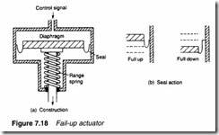
A typical actuator is shown in Figure 7.18. The control signal is applied to the top of a piston sealed by a flexible diaphragm. The downward force from this pressure (P x A) is opposed by the spring compression force and the piston settles where the two forces are equal, with a displacement proportional to applied pressure. Actuator gain (displacement/pressure) is determined by the stiff ness of the spring, and the pressure at which the actuator starts to move (0.2 bar say) is set by a pre-tension adjustment.
Figure 7.18b illustrates the action of the rubber diaphragm. This ‘peels’ up and down the cylinder wall so the piston area remains constant over the full range of travel.
The shaft of the actuator extends for increasing pressure, and fails in a fully up position in the event of the usual failures of loss of air supply, loss of signal or rupture of the diaphragm seal. For this reason such an actuator is known as a fail-up type.
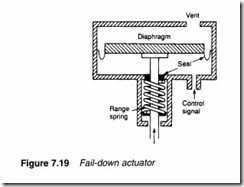
In the actuator of Figure 7.19, on the other hand, signal pressure is applied to the bottom of the piston and the spring action is reversed. With this design the shaft moves up for increasing pressure and moves down for common failure modes. This is known as a fail-down or reverse acting actuator.
One disadvantage of this design is the need for a seal on the valve shaft.
Where safety is important, valve and actuator should be chosen to give the correct failure mode. A fuel valve, for example, should fail closed, while a cooling water valve should fail open.
Valve actuators tend to have large surface areas to give the required force, which means a significant volume of air is above the piston. Valve movement leads to changes in this volume, requiring air to be supplied from, or vented by, the device providing the pressure signal. A mismatch between the air requirements of the actuator and the capabilities of the device supplying pressure signal results in a slow, first order lag response.
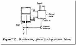
The net force acting on the piston in Figures 7.18 and 7.19 is the sum of force from the applied pressure, the opposing spring force and any dynamic forces induced into the valve stem from the fluid being controlled. These dynamic forces therefore produce an offset error in valve position. The effect can be reduced by increasing the piston area or the operating pressure range, but there are limits on actuator size and the strength of the diaphragm seal. In Figure 7.20 a double-acting piston actuator operating at high pressure is shown. There is no restoring spring, so the shaft is moved by application of air to, or venting of air from, the two sides of the piston. A closed loop position control scheme is used, in which shaft displacement is compared with desired displacement (ie, signal pressure) and the piston pressures adjusted accordingly. The arrangement of Figure 7.20 is called a valve positioner, and correctly positions the shaft despite dynamic forces from the valve itself.
Valve positioners
A valve positioner is used to improve the performance of a pneu matically-operated actuator, by adding a position control loop around the actuator as shown in Figure 7.21. They are mainly used:
• to improve the operating speed of a valve;
• to provide volume boosting where the device providing the control signal can only provide a limited volume of air. As noted previously a mismatch between the capabilities of driver and the requirements of an actuator results in a first order lag response with a long time constant;
• to remove offsets resulting from dynamic forces in the valve (described in the previous section);
• where a pressure boost is needed to give the necessary actuator force;
• where a double-acting actuator is needed (which cannot be con trolled with a single pressure line).
There are two basic types of valve positioner. Figure 7.22 shows the construction of a valve positioner using a variation of the force balance principle described earlier. The actuator position is con verted to a force by the range spring. This is compared with the force from the signal pressure acting on the input diaphragm. Any mismatch between the two forces results in movement of the beam and a change in the flapper-nozzle gap.
If the actuator position is low, the flapper-nozzle gap decreases, causing a rise in pressure at point A. This causes the spool to rise, connecting supply air to output 1, and venting output 2, resulting in the lifting of the actuator. If actuator position is high,
the flapper-nozzle gap increases and pressure at A falls causing the spool to move down applying air to output 2 and venting output 1, which results in the actuator lowering. The actuator thus balances when the range spring force (corresponding to actuator position) matches the force from the input signal pressure (corresponding to the required position) giving a constant flapper-nozzle gap.
The zero of the positioner is set by the linkage of the positioner to the valve shaft and the range by the spring stiffness. Fine zero adjustment can be made by a screw at the end of the spring.
The second type of positioner, illustrated in Figure 7.23, uses a motion balance principle. The valve shaft position is converted to a small displacement and applied to one end of the beam controlling the flapper-nozzle gap. The input signal is converted to a displacement at the other end of the beam. The pressure at A resulting from the flapper-nozzle gap is volume boosted by an air relay which passes air to, or vents air from, the actuator, to move the shaft until the flapper-nozzle gap is correct. At this point, the actuator position matches the desired position.
Positioners are generally supplied equipped with gauges to indicate supply pressure, signal pressure and output pressures, as illustrated
in Figure 7.24 for a double-acting actuator. Often, bypass valves are fitted to allow the positioner to be bypassed temporarily in the event of failure with the signal pressure sent directly to the actuator.

