■ AN OVERVIEW OF RECIPROCATING ENGINES
Despite its simplicity, the reciprocating engine (basically a piston-cylinder device) is one of the rare inventions that has proved to be very versatile and to have a wide range of applications. It is the powerhouse of the vast majority of automobiles, trucks, light aircraft, ships, and electric power generators, as well as many other devices.
The basic components of a reciprocating engine are shown in Fig. 8–10. The piston reciprocates in the cylinder between two fixed positions called the top dead center (TDC)—the position of the piston when it forms the smallest volume in the cylinder—and the bottom dead center (BDC)—the position of the piston when it forms the largest volume in the cylinder. The distance between the TDC and the BDC is the largest distance that the piston can travel in one direction, and it is called the stroke of the engine. The diameter of the piston is called the bore. The air or air–fuel mixture is drawn into the cylinder through the intake valve, and the combustion products are expelled from the cylinder through the exhaust valve.
The minimum volume formed in the cylinder when the piston is at TDC is called the clearance volume (Fig. 8–11). The volume displaced by the piston as it moves between TDC and BDC is called the displacement volume. The ratio of the maximum volume formed in the cylinder to the minimum (clearance) volume is called the compression ratio r of the engine:
Notice that the compression ratio is a volume ratio and should not be confused with the pressure ratio.
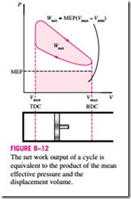
Another term frequently used in conjunction with reciprocating engines is the mean effective pressure (MEP). It is a fictitious pressure that, if it acted on the piston during the entire power stroke, would produce the same amount of net work as that produced during the actual cycle (Fig. 8–12). That is,
The mean effective pressure can be used as a parameter to compare the performances of reciprocating engines of equal size. The engine with a larger value of MEP will deliver more net work per cycle and thus will perform better.
Reciprocating engines are classified as spark-ignition (SI) engines or compression-ignition (CI) engines, depending on how the combustion process in the cylinder is initiated. In SI engines, the combustion of the air–fuel mixture is initiated by a spark plug. In CI engines, the air–fuel mixture is self- ignited as a result of compressing the mixture above its self-ignition temperature. In the next two sections, we discuss the Otto and Diesel cycles, which are the ideal cycles for the SI and CI reciprocating engines, respectively.

