The influence of changing pipeline diameter
If the required increase in material flow rate is greater than that which can reasonably be obtained by optimizing the existing system, it will probably be necessary to increase the size of the pipeline. If it can be established that the blower is over-rated for the existing plant, in terms of volumetric flow rate, it is possible that the same blower could be used with a larger bore line. In order to investigate this possibility, conveying characteristics for different sizes of pipe are necessary. For the purposes of demonstrating the potential influence of pipe bore the conveying characteristics for the cement in the 76 mm bore line in Figure 21.3 have been scaled in proportion to pipe section area.
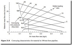
In Figure 21.8 the conveying characteristics for the material conveyed through a 100 mm bore pipe are presented. If the reference condition used in Figure 21.3, to show the influence of air mass flow rate, is taken again, both the possibility of using the same blower with a larger size pipe and the influence of pipe bore can be investi- gated. In the earlier case a blower capable of delivering 0.18 kg/s of air at 0.6 bar gauge was considered. For the 76 mm bore line in Figure 21.3 it was shown that the material flow rate would be 5.5 tonne/h. This, however, could be increased to 7.7 tonne/h by
using an off-take for 50 per cent of the air, and to 11.9 tonne/h by reducing the speed of the blower, since the blower was over-rated.
The reference condition in Figure 21.8 is denoted by point F. With an air mass flow rate of 0.18 kg/s and a supply pressure of 0.6 bar gauge it will be seen that conveying of the cement in a 100 mm bore line is close to the ideal condition. The velocity of the air at the material feed point into the pipeline would be about 12 m/s. This provides an adequate safety margin in terms of the minimum conveying air velocity for the mater- ial, as shown in Figure 21.6, and so no change in blower operating conditions would need to be made. The solids loading ratio of the cement would be about 20 and the material flow rate 12.3 tonne/h. There is even scope for an improvement on this by reducing the speed of the blower as the operating condition is well above the minimum.
In Figure 21.9 the conveying characteristics for the material conveyed through a 125 mm bore pipeline are presented. If the same blower supply conditions of 0.18 kg/s at 0.6 bar gauge are superimposed it will be seen that the operating point, denoted by the reference G, is beyond the range of the conveying characteristics. The velocity of the air at the material feed point would only be about 7 m/s and so it is unlike that con- veying would be possible. The theoretical value of solids loading ratio would be about If the rotor speed of the blower is increased to about 1900 rev/min, the air mass flow rate would be increased to 0.25 kg/s and this should be ideal for conveying the cement through a 125 mm bore pipeline. From the blower characteristics in Figure 21.5 it will be seen that the delivery pressure would be reduced to about 0.50 bar with the same 16 kW power input. The new blower operating conditions are shown on Figure 21.9 at point H.
From this it will be seen that the material flow rate would be about 15.7 tonne/h. The solids loading ratio of the material would be about 18 and the conveying
line inlet air velocity about 11 m/s, which would be quite satisfactory as shown on Figure 21.6.
System potential
If the required material mass flow rate is greater than that which can be achieved with the existing blower, then a larger bore line and a new blower would be required. From Figure 21.9 the potential conveying capacity of a 125 mm bore pipeline can be seen. If a blower capable of supplying 0.25 kg/s at 0.8 bar gauge is used, for example, a material flow rate of almost 30 tonne/h could be achieved.
If such a large increase in material flow rate is required, however, it would also be necessary to check whether the existing feeding device is capable of delivering at such a rate, and whether the filtration unit is capable of handling the increase in both air and material satisfactorily. In the above case study it has been assumed that the feeding device would deliver the appropriate flow rate into the conveying line each time. It is, of course, essential that this should be the case. If insufficient material is fed into the conveying line the capability of the blower, in terms of pressure, will not be achieved for the resistance of the line will be insufficient.

