Multiple use systems
Introduction
Not all pneumatic conveying systems are dedicated to the conveying of a single material over just one distance. In many cases several materials have to be conveyed to a number of different reception points. In a manufacturing process a single pipeline may be used to convey a diverse range of materials from a number of supply hoppers to a sin- gle delivery point for blending. In many industries, such as glass and food, a wide variety of materials have to be conveyed by a common system, since there is a requirement to deliver a given ‘menu’ for a particular process.
In ship off-loading a single line may be used to unload several different materials and to convey them to separate locations. Road and rail vehicles, and ships with their own off-loading facilities, are often required to discharge their materials into reception silos through pipelines of varying distances and geometry. In all of these cases it is essential that each material should be conveyed successfully, but each material may have different conveying characteristics and as a consequence the air requirements for the conveying of different materials, and the material flow rates achieved, can vary significantly. Conveying distance can also have a significant influence on conveying performance [1].
Some of the materials to be transported may be capable of being conveyed in dense phase, and hence at low velocity, while others may have no dense phase capability and will have to be conveyed in dilute phase with a high conveying air velocity. The convey- ing performance of different grades of the same material can also differ widely. Alumina and fly ash are two common materials that can come in a number of different grades. It is often necessary for different grades of either of these materials to be conveyed by a common system.
The design of these systems, therefore, requires very careful consideration. Fly ash, for example, collected in air pre-heater and economizer hoppers is usually coarse, and in general can only be conveyed in dilute phase, while the ash collected in the precipitator hoppers is usually fine and can normally be conveyed very easily in dense phase. By employing stepped pipelines, different materials such as these can be conveyed quite easily by a common pneumatic conveying system.
Multiple material handling
In many pneumatic conveying systems several materials may have to be handled by the one system and pipeline. The conveying characteristics present the necessary relation- ships between the main conveying parameters for a particular material in a specified pipeline and enable a system design to be carried out. If the materials have different con- veying characteristics particular care will have to be taken in the specification of the cor- rect air flow rate, and provision should be made for the control of the air flow rate. It is also most unlikely that it would be possible to achieve the same flow rate with each type of material.
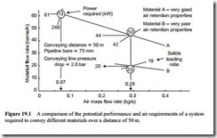
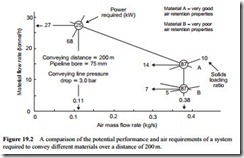
These points can be explained by reference to Figures 19.1 and 19.2, which are plots of material flow rate against air mass flow rate. Lines of constant conveying line pressure drop have been drawn for two different materials. For Figure 19.1 the data for material A comes from Figure 15.5 and for material B from Figure 15.6.
If an air flow rate in excess of the minimum value is used to convey each material it will be seen from Figure 19.1 that material A will require 0.07 kg/s of air and mater- ial B 0.29 kg/s. In each case the material is conveyed through a 50 m long pipeline of 75 mm bore with a conveying line pressure drop of 2.0 bar.
If the air supply available to the system represented in Figure 19.1 was only speci- fied for material A, at 0.07 kg/s, it would not be possible to convey material B at all. Thus the air supply for the system would have to be based on material B. If the full air flow rate of 0.29 kg/s was used to convey material A, however, the flow rate achieved would only be 44 tonne/h. With an air flow rate of 0.07 kg/s a flow rate of 61 tonne/h could be achieved with material A.
It should be noted that this much higher material flow rate can be achieved with only one quarter of the power required to convey material B, or material A at 44 tonne/h if the same air flow rate is used. A similar situation is shown in Figure 19.2
with a 200 m long pipeline of the same bore. In this case the potential reduction in flow rate of material A is particularly marked since this is a relatively long pipeline of small bore. Full sets of conveying characteristics for materials A and B conveyed over 200 m are presented in Figures 15.9 and 15.10.
It is clear from the data presented on Figures 19.1 and 19.2 that some form of control of the air supply is required. Control of the material flow rate is also required, of course. In both cases presented a considerable increase in the flow rate of material A could be achieved if the air flow rate could be reduced. Apart from the increase in material flow rate there is also the potential for considerable energy savings. In the case presented in Figure 19.1 the increase of 17 tonne/h could be achieved with a 40 kW saving in power, and in the case presented in Figure 19.2 the proportions are even greater.
Air supply control
The control that can be applied to the air supply depends to a large extent upon the type of air mover used or the source of air available. The performance characteristics of the air mover must be considered in order to determine the best means of control, as dis- cussed in relation to Figures 6.5 and 6.6. The initial choice of air mover, of course, is par- ticularly important, for in some cases it will not be possible for the one machine to meet the full range of duties.
With some machines it may not be possible to obtain independent control of flow rate and pressure, and with others it may prove difficult to achieve the potential energy sav- ing. If a general high pressure air supply service is available, choked flow nozzles can be used most effectively to control the air flow rate at a given pressure, but the energy sav- ing will depend upon the air supply system employed. The use of choked flow nozzles was considered in Section 10.4. With some pneumatic conveying systems operating with their own self-contained air supply, others using a general service supply, and with such a wide range of air movers available, each with it own operating characteristics, it is quite impossible to offer general recommendations on system control in this respect.
High, low and negative pressure systems all require separate treatment, with control of the air mover being necessary in some cases, and control by means of the air supply line being possible in other cases. The important points to bear in mind are that different materials are quite likely to have different volumetric air flow and power requirements, and that the air supply should be capable of meeting both the maximum demand and being conveniently controlled to lower demand levels.
Material flow control
Since different materials have different flow rate capabilities in a given conveying line, due consideration should be given to the material feeding device. Changes in material feed rate must clearly be made, for if a design was based on the conveying of material B only, for example, the pipeline would be considerably under-utilized for the conveying of material A. Alternatively, if the design was based on material A, the pipeline would almost certainly block when conveying material B, even if the air flow rate was correct.
The feeding device, therefore, should be capable of operating satisfactorily and con- veniently over the range to be encountered. With volumetric feeders, such as rotary valves and screws, differences in material bulk densities should also be taken into account as well as differences in flow rate.

