Alternative electrical designs of motors
Synchronous motors
Separately exited
For high powers, typically greater than 5000 kW (7000 hp}, for some high speed and also for some special low power applications, the most usual solution is a synchronous motor, which has relatively lower rotor losses, and is therefore simpler to keep cool.
Synchronous motors may be fitted with a permanent magnet generator to provide the rotor field or a wound exciter on the rotor. With a synchro nous motor there is no slip.
Switched reluctance motors
Switched reluctance motors are both simple and robust in construction.
The rotor of a switched reluctance motor comprises electrical steel laminations mounted on the motor shaft. Unlike most technologies, the switched reluctance motor has no rotor windings or permanent magnets. The motor is self-excited and uses a transversely laminated rotor with a special geometry to generate a suitable field.
The stator is similarly straightforward, comprising a core of laminated electrical steel and a number of independent phase windings.
The operation of the switched reluctance motor is best described in conjunction with Figure 6.5.
Figure 6.5: Schematic representation of switched reluctance power converter and motor Diagonally opposed poles are energized, and due to the current flowing, torque is produced in the associated rotor poles. As the rotor poles align, the converter applies energisation to the next pair of poles, to maintain rotation. Most systems require a simple position sensor attached to the rotor to enable the converter to switch correctly.
Switched reluctance motors must be operated in conjunction with a suitable drive unit. This ensures their suitability for variable speed applica tions, but may limit their application for lower power fixed-speed require ments where the cost of the controller may not be justifiable.
Permanent magnet (PM) motors
In recent years, more and more emphasis has been placed on overall high-efficiency characteristics. Due to this, permanent magnet motors are being increasingly considered for many applications.
AC permanent magnet motors generally have stator windings similar to induction motors but they use permanent magnets in the rotor instead of a squirrel cage. DC permanent magnet motors have two or four windings and use electronic commutation to achieve the rotating stator field. The permanent magnet rotor synchronously follows the rotating field in the stator and responds to varying frequencies of the field in a way which can be considered quite similar to the induction motor.
Since the magnet requires no electrical power, unlike an induction machine rotor, the permanent magnet motor is inherently efficient especially at reduced speed and partial loads. The efficiency of a permanent magnet motor tends to be higher than those for an asynchro nous motor of similar rating.
Permanent magnet motors have traditionally been used in large numbers for specialised applications, such as spinning machines and machine tools. Due to the requirement of energy saving, high efficiency has become a major selling point in many areas, such as domestic and OEM applications including air conditioners, fans and pumps. However, this technology is maturing and it is increasingly being applied in industrial applications, including pumping. PM motors are limited only by the peripheral speed of the rotor, and are available for a wide range of small power high-speed applications and increasingly in higher power slow speed designs.
Some permanent magnet motor designs require a variable speed drive in order to operate, which has the benefit of enabling energy saving speed control.
The use of a variable speed drive does tend to increase the initial instal lation cost, which may be difficult to justify in applications where variable speed is not required. However, recent developments in ‘line-start’ permanent magnet motors (which can operate directly from the network mains supply) enable the efficiency benefits of permanent magnet motors to be realised without the cost penalty of a variable speed drive.
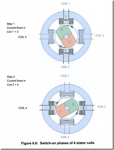
The principles of electronically commutated permanent magnet motors Figure 6.6 shows simplified, the appropriate switch-on phases (current flow) of 4 stator coils. Due to the current flowing in the stator pole windings, a magnetic stator field with north and south pole is formed depending upon the relevant current direction. The permanent magnet rotor, with a constant magnetic field rotating in the stator field, is made to rotate by the attraction and rejection forces of unequal and equal poles. The uniform rotation results from the current flow of the individual stator coils, which circulates with time .
WARNING – Great care needs to be exercised with PM motors in applications where energy can be taken from the driven load, as they also operate as permanently excited generators. This means that back flow in pumping installations, which causes reverse rotation, must be avoided when permanent magnet motors are used.
DC motors
The conventional DC motor has a wound stator to provide a field. A wound rotor (the armature) is fed by a commutator, which switches the power to the appropriate windings to give an offset magnetic field to develop the torque.
Traditionally, the lower cost, greater simplicity, and ease of control of DC drives compared to AC drives, was much more significant than the higher cost and lower efficiency of DC motors. DC drives were therefore the norm for speed control applications for many years. However, the higher maintenance requirements and generally lower environmental protection of DC motors are often held against this technology.
DC drives are still used where some advantages are perceived to exist, but even these are being eroded as AC drive technology improves. Developments such as flux vector control have now allowed AC drives to be used in high performance and highly dynamic applications where accurate torque/speed control is required. This used to be the exclusive benefit of DC drives.
DC permanent magnet motors are described in Section 6.3.1.3.
Motor construction and cooling
All electric motors have losses, mainly manifested as heat, which must be dissipated. This is normally to the ambient air, and a conventional motor is designed to dissipate this heat when running at fixed speed and full output.
Dry installed motors
The majority of electric motors are designed to operate with ambient air crossing the motor frame to achieve cooling. Fans mounted directly to the motor shaft generally achieve the airflow. In special cases, especially with large power motors, a heat exchanger, either air/air or water/air, may be used.
The levels of ingress protection for the motor and the various cooling
forms are defined in the IEC and NEMA standards.
Submersible pump motors
In principle, most submersible pumps use squirrel-cage induction motors that are not significantly different from the typical non-submersible induction motors, except with regard to cooling.
Submersible pump motors, which are not provided with internal or external cooling systems, are cooled by full or partial submergence in the pumped liquid. In such cases motor cooling is not normally affected by speed reduction when driven by a VFD.
Submersible pump motors, above a certain size, are provided with various types of cooling systems to dissipate the heat generated from motor losses. Some of these designs have minimum speed requirements that must be met to assure proper cooling.
For installations which can be either dry or immersed, a submersible pump motor is normally provided with a cooling jacket around the stator casing, inside which a cooling liquid is circulated.
Submersible borehole pump motors must be installed such that the flow of the pumped liquid provides sufficient motor cooling. This is often achieved by the use of a shroud if units are used in non-confined areas.
Wet rotor motors (canned motors)
In other applications a “wet rotor” or “canned motor” construction is utilised, with a physical non-magnetic barrier between the stator and rotor of the machine. The use of a canned design eliminates the requirement for seals around rotating elements.
As it is relatively insensitive to the gap between the stator and rotor, permanent magnet motors tend to be more and more widely used in small power water pumps, up to 4 kW (5 hp) when the preferred solution is the so-called “wet rotor” configuration.
The efficiency benefits of permanent magnet motors also apply to “wet” rotor motors. Table 6.3 shows a comparison of efficiencies for an asyn chronous “wet” induction motor and a “wet” permanent magnet synchronous motor, of equal size and gap.
Other special designs include motors, which are totally liquid filled (water or oil), or allow free ingress of the pumped medium.
Motor starting
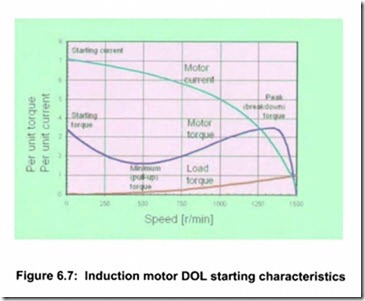
Fixed speed motors will normally be connected direct on line (DOL) to the electrical supply network, and will cause a high starting current to flow on switching. The magnitude of this current may be problematical with larger
Motors
power motors or weak power supplies. There are several alternative means of providing control of this starting current, which can avoid network problems. Typical starting characteristics are shown in Figure 6.7.
Without control, most motors will have a limited number of starting cycles per hour, due to the slip energy causing a temperature rise in the rotor during starting .
Variable speed drives eliminate high starting currents and rotor heating on starting and hence there are generally no restrictions on the number of starts. It is also possible to reduce the power rating of standby generating equipment because of the lower peak current. Lower peak currents can also reduce peak demand charges.
Currently employed starting methods include “reduced voltage” starters such as star-delta (Wye-delta), autotransformer or electronic soft starters, however they all result in reduced torque availability at breakaway. In general this is not a problem with rotodynamic pumps, but can be problematic with some PD pump types.
Formerly one of the most common solutions was to use a wound rotor motor, which has rotor resistance starting. However, the higher life cycle costs (initial cost, maintenance cost and reduced efficiency) of this solution has caused its demise.


