Venturi feeders
Since the basic problem with feeding positive pressure systems is that the air leakage arising from the adverse pressure gradient can interfere with the flow of the material into the pipeline, this situation can be improved, to a certain extent, by using venturi feeders. These work on the principle of reducing the pipeline cross-sectional area in the region where the material is fed from the supply hopper, as shown in Figure 3.16.
It will be seen that there are no moving parts with this type of feeding device, which has certain advantages with regard to wear problems. There are, however, no inherent means of flow control either, and so this has to be provided additionally.
A consequence of the reduction in flow area is an increase in the entraining air velocity and a corresponding decrease in pressure in this region. With a correctly designed venturi the static pressure at the throat should be the same as that in the sup- ply hopper which, for the majority of applications, is atmospheric pressure. This then encourages the material to flow more readily under gravity into the pipeline, since under these conditions there is no leakage of air in opposition to the material feed.
In order to keep the throat at atmospheric pressure, and also of a practical size that will allow the passage of material, and for it to be readily conveyed, a relatively low limit has to be imposed on the air supply pressure. These feeders, therefore, are usually incorporated into systems that are required to convey free flowing materials at low flow rates over short distances. Since only low pressures can be used with the basic type of venturi feeder shown in Figure 3.16, a standard industrial type of fan is all that is needed to supply the air required.
Commercial venturi feeder
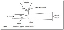
To fully understand the limitations of this type of feeder the thermodynamic relation- ships need to be followed and these are presented in Chapter 10. In this it is shown that in a 100 mm bore pipeline, with air supplied at 0.2 bar gauge, the throat diameter would have to be about 36 mm. Although venturis capable of feeding materials into conveying systems with operating pressure drops of 0.3 bar are commercially avail- able, the pressure drop across the venturi can be of the same order. Such a venturi is shown in Figure 3.17.
Venturi feeders, however, are yet another type of feeder that can have its operating pressure range extended significantly, should this be required, by means of incorporating the device in a lock hopper system. This is also considered further in Chapter 4.
For an operating pressure drop of 0.3 bar and a 50% energy recover rate in the venturi this means that the air supply will have to be at about 0.6 bar gauge and consequently the air will have to be supplied by a positive displacement blower. Since there are no moving parts these feeders are potentially suitable for abrasive and friable materials. Care must be exercised in using venturis to feed such materials into the con- veying line, however, for the high air velocity in the throat may lead to considerable erosion and particle degradation in this region. To counter the wear problems venturis can generally be obtained with wear resistant sections.
A particular advantage of the venture feeder, compared with many other feeding devices, is that it is small, occupies little space, and can be relatively cheap. It also requires very little headroom, which is often of benefit where pneumatic conveying systems may need to be fitted into existing plant with little room for modifications. They are often used in combustion applications, for the firing of coal dust and petroleum coke into boilers and furnaces, where individual burners may be fired directly from their own venturi feeder.
Flow control
Since experience has shown that these feeders are best suited to the handling of free flowing materials, care must be taken to continuously control the flow of materials, otherwise a blockage may occur. There is no inherent means of flow control, as men- tioned earlier, and so this means that the venturi could either be fed from a belt, screw, rotary valve or vibratory feeder. Alternatively a supply hopper could be used if fitted with a trickle valve, calibrated orifice plate or gate/slide valve. A sketch of some mechanical feed control devices is given in Figure 3.18.
A sketch of some of the direct hopper fed control devices is given in Figure 3.19. A butterfly valve, for example, was illustrated with Figure 3.17. A problem with this class of control is that they are vulnerable to changes in material properties.
They are usually calibrated and set up on commissioning of the plant, but a slight change in particle size, shape or moisture content will affect the balance of the setting for the material and so change the flow rate. These are very simple and cheap devices but if strict control of the feed rate is required they do need to be provided with a sep- arate controlling device, where possible, operating from a feedback signal based on conveying line pressure drop.
