Vane pumps
Vane pumps have an inherent advantage as compared with gear pumps in that their basic design and construction minimizes the amount of leakage that occurs in gear pumps between the teeth gaps and also between the teeth and the pump housing. This is accomplished by using spring or hydraulically loaded vanes slotted into a driven rotor. Vane pumps generate a pumping action by causing the vanes to track along a ring. The pumping mechanism of a vane pump essentially consists of a rotor, vanes, ring and a port plate with kidney-shaped inlet and outlet ports. A basic type of vane pump is illustrated in Figure 3.10.
The rotor in a vane pump is connected to the prime mover by means of a shaft. The vanes are placed in radial slots milled into the rotor, which in tum is placed off-center inside a cam ring. When the shaft turns the rotor, the vanes are thrown outward against the cam ring by the centrifugal force and track along the ring, thereby providing a hydraulic seal. The expansion of volume capacity which is indicated by the extension of the vanes as they move through the inlet, allows the atmospheric pressure to push fluid into the pump. The fluid is carried around to the outlet by the vanes whose retraction causes the fluid to be expelled. The pump capacity in vane pumps is determined by vane throw, vane cross-sectional area and the speed of rotation. Vane pumps usually have lower capacity and pressure ratings than gear pumps. But one of the biggest advantages with vane pumps is the high volumetric efficiencies achieved on account of reduced leakage.
Detailed pump operation
Since the rotor is positioned off-center to the ring during one half of a rotor revolution, the volume between the rotor and the ring increases, thereby permitting the atmospheric pressure acting on the oil tank to force the oil into the pump. This forms the suction process.
During the second half of the rotor revolution, the ring surface will push the vanes back into the rotor slots, and the volume is reduced. This positively ejects the fluid trapped between the ring and the rotor to the outlet port.
Since there are no ports in the ring, a port plate is used to separate the incoming fluid from the outgoing fluid. The port plate fits over the ring, rotor and vanes. The inlet port of the port plate is located at the place where increasing volume is generated and the outlet port at the place where decreasing volume is generated.
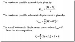
All fluids enter and exit the pumping mechanism through the port plate. The off-center distance between the cam and rotor is known as eccentricity. When the eccentricity is zero, there will be no flow.
The following analysis and nomenclature is applicable to a vane pump: Let
De be the diameter of the cam ring
Dr be the inside diameter of the rotor
L be the width of the rotor
vd be the displacement volume of the pump
N be the speed of the pump
E=x be the maximum possible eccentricity
E be the eccentricity and
Vdmax be the maximum possible volumetric displacement.
Classification of vane pumps
Vane pumps can further be classified as:
• Balanced vane pumps and
• Variable displacement vane pumps.
Let us discuss the above two categories in detail.
3.5.1 Balanced vane pump
In the unbalanced vane pump, one half of the pumping mechanism experiences pressure that is less than atmospheric, while the other half is subjected to full system pressure. This difference in pressure between the outlet and inlet ports tends to create a severe load on the vanes which along with a large side load on the rotor shaft can lead to bearing failure. It is with a view towards compensating for this deficiency that the concept of balanced vane pump was thought of. The functions of a balanced vane pump are similar to the unbalanced pump except that in the former, the cam ring is cam-shaped or elliptical along with the presence of two intake and two outlet ports that are connected inside the housing.
In our discussion on unbalanced vane pumps, we find that two very different pressures are involved during the course of the pump operation. During one half of the rotor revolution, there is a negative pressure and during the other half revolution of the rotor, the pump is subjected to full system pressure. This results in the side loading of the shaft, which could be severe when high system pressures are encountered. In order to compensate for this, the ring is changed from circular to elliptical shape. The two high pressure outlet ports are located 180° apart. Because they are located on the opposite sides of the housing, excessive force or pressure buildup on one side is canceled out by equal but opposite forces on the other side. Since the forces acting on the shaft are balanced, the shaft side load is eliminated. In other words, the two pressure quadrants oppose each other and the forces acting on the shaft are balanced. Flow in a balanced vane pump is created very much in the same manner as an unbalanced vane pump, except that there are two suction and discharge cavities instead of one.
A balanced vane pump consists of a cam ring, rotor, vanes and a port plate with inlet and outlet ports opposing each other as shown Figure 3.11. The advent of balanced type vane pumps has led to a significant increase in bearing lifetime, almost about 10-20 times over that of the unbalanced type, in addition to significantly increasing the pressure and speed ratings of these units. Another important point to be noted is that a majority of the constant volume, positive displacement vane pumps used in industrial applications are generally of the balanced type.
Vane loading
For a vane pump to operate satisfactorily, it is extremely important for a positive seal to exist between the vane tip and the cam ring. The vane pump relies on the centrifugal force to draw the vanes outward against the cam ring to achieve a positive seal. For this reason the minimum operating speed for most vane pumps is 600 rpm.
As the system pressure rises, a tighter seal is required between the vane tip and cam ring in order to minimize internal leakage. For achieving better sealing at high pressures, industrial vane pumps direct system pressure to the underside of the vane. Although this ensures good positive sealing, there is a major disadvantage. By hydraulically loading the vane, the force with which the vane tracks along the cam ring becomes proportional to the discharge pressure. So, at times when the pressure is too high, the force loading the vane is excessive, leading to premature wear of the cam ring and vanes. As a compromise between achieving the best sealing and the least wear, the vanes are only partially loaded.
One way of eliminating this vane loading is by the use of vanes with a chamfer or a beveled edge. Such an arrangement results in the complete underside of the vane area along with a fairly large portion of vane top area, getting exposed to the system pressure. This results in a balance. The pressure which acts on the unbalanced area is in tum, the force loading the vane. The use of bevel-edged vanes has its limitations and is not suitable for application in high-pressure pumps.
Variable displacement vane pump
A positive displacement vane pump delivers the same volume of fluid for each revolution. Industrial pumps generally operate at speeds of 1200 or 1800 rpm indicating the fairly constant nature of the pump flow rate.
The flow rate from the pump in most hydraulic applications needs to be variable, more often than not. One way of achieving this is by varying the speed of the prime mover. However this is not economically practical and therefore, the only other way this can be done is by changing the pump displacement.
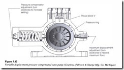
The amount of fluid that is displaced by a vane pump is determined by the difference between the maximum and minimum distances by which the vanes are extended and the vane width. While the pump is in operation, we can do nothing, to change the width of the vane. However, the distance by which the vanes are extended can be varied. This is done by making a provision for altering the position of the cam ring relative to the rotor. Such an arrangement enables us to achieve a variable volume from a vane pump. These pumps are known as variable displacement vane pumps. The pumping mechanism of a variable volume vane pump basically consists of a rotor, vanes, cam ring, port plate, thrust bearing for guiding the cam ring and a pressure compensator or hand wheel by which the position of the cam ring can be varied relative to the rotor.
In Figure 3.12, the provision made for changing the position of the cam ring is a screw, which can be manually operated.
Variable displacement pressure compensated vane pump (Courtesy of Brown & Sharpe Mfg. Co, Michigan)
Variable volume vane pumps are unbalanced pumps. Notwithstanding the fact that the rings in these pumps are actually circular and not cam-shaped, they are still referred to as cam-rings.
Working principle
With an inward movement of the screw, the rotor is held off-center with respect to the cam ring (eccentricity). The turning of the rotor induces pumping action. When the screw is drawn outward, the eccentricity is not as much as it was before and therefore the delivery volume is reduced. When the screw is drawn outwards completely, the cam ring centers with the rotor or in other words the eccentricity is zero, resulting in a condition where no increasing or decreasing volume is produced. Hence in spite of the rotor continuing to turn, no pumping action takes place.
Pressure compensation in variable displacement vane pumps
Variable volume vane pumps are generally pressure compensated, which means that when the discharge pressure reaches a certain set value, the pumping action ceases. This is accomplished by using an additional spring called the ‘compensator spring’ to offset the cam ring.
Initially when the pump discharge pressure is zero, the eccentricity is at a maximum and the spring force will keep the cam ring in the extreme right position. As the discharge pressure increases, it acts on the inner contour of the cam ring and pushes the cam ring towards the left against the spring force, thereby reducing the eccentricity.
When the discharge pressure rises further and becomes high enough to overcome the entire spring force, the compensator spring is compressed until zero eccentricity is achieved. Thus, pumping action ceases and there is no more flow except for minor leakages.
System pressure is therefore limited to the setting of the compensator spring. These pumps therefore ensure their own protection against excessive pressure build-up in the circuit and do not rely on the safety control devices of the hydraulic system.
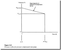
A flow vs a pressure graph relationship for a variable volume pressure compensated pump is shown in Figure 3.13.
From the graph, the following can be noticed:
1. Maximum eccentricity gives maximum flow
2. Flow reduces with increase in discharge pressure
3. Zero flow condition results when the eccentricity is zero.
The volumetric efficiency of a good vane pump normally lies between 90 and 95%.


