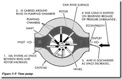
Vane Pumps
Vane-type hydraulic pumps generally have circularly or elliptically shaped interiors and flat end plates. Figure 3-9 illustrates a vane pump with a circular interior. A slotted rotor is fixed to a shaft that enters the pump-housing cavity through one of its end plates. A number of small rectangular plates or vanes are set into the slots of the rotor. As the rotor turns, centrifugal force causes the outer edge of each vane to slide along the surface of the
housing cavity. The cavities formed by the vanes, the end plates, the housing, and the rotor enlarge and shrink as the rotor and vane assembly rotates. An inlet port is installed in the housing so fluid may flow into the cavities as they enlarge. An outlet port is pro vided to allow the fluid to flow out of the cavities, as they become small.
The pump shown in Figure 3-9 is referred to as an unbalanced pump because all of the pumping action takes place on one side of the rotor. This causes a side load on the rotor. Some vane pumps are constructed with an elliptical housing that forms two sep arate pumping areas on opposite sides of the rotor. This cancels the side load. This type of pump is referred to as a balanced vane.
Usually, vane pumps are fixed-displacement and pump only in one direction. There are some designs of vane pumps that provide variable flow. Vane pumps are generally restricted to service where pressure demand does not exceed 2,000 psi. Wear rates, vibration, and noise level increase rapidly in vane pumps as pressure demands exceed 2,000 psi.
RECIPROCATING PUMPS
The term reciprocating is defined as back-and-forth motion. In the reciprocating pump it is the back-and-forth motion of pistons inside of cylinders that provides the flow of fluid. Reciprocating pumps, like rotary pumps, operate on the positive principle: that is, each stroke delivers a definite volume of liquid to the system.
One major limitation of reciprocating pumps is the intermittent flow that they pro duce. The back-and-forth motion generates pulses of volume that create vibration and turbulent flow within the hydraulic system. These systems must include an accumulator downstream from the pump to dampen these pulses.
Hand Pumps
There are two types of manually operated reciprocating pumps-the single-action and the double-action. The single-action pump provides flow during every other stroke, while the double-action provides flow during each stroke. Single-action pumps are frequently used in hydraulic jacks.
A double-action hand pump is illustrated in Figure 3-10. Tiris type of pump is used in some applications as a source of emergency hydraulic power or for testing hydraulic systems.
This type of pump consists of a cylinder, a piston containing a built-in check valve (A), a piston rod, an operating handle, and a check valve (B) at the inlet port. When the piston is moved to the left, the force of the liquid in the outlet chamber and spring tension cause valve A to close. This movement causes the piston to force the liquid in the outlet chamber through the outlet port and into the system. This same piston movement causes a low-pressure area in the inlet chamber and the liquid, at atmo spheric pressure, in the reservoir acting on check valve B causes its spring to com press. Thus, opening the check valve allows liquid to enter the inlet chamber.
When the piston completes this stroke to the left, the inlet chamber is full of liquid. Tiris eliminates the pressure difference between the inlet chamber and the reservoir, thereby allowing spring tension to close check valve B. When the piston is moved to the right, the force of the confined liquid in the inlet chamber acts on check valve A. This action compresses the spring and opens the valve, allowing the liquid to flow from the intake chamber to the outlet chamber. Because of the area occupied by the piston rod, the out let chamber cannot contain all the liquid discharged from the inlet chamber. Since liquids do not compress, the extra liquid is forced out of the outlet port and into the system.
Piston Pumps
All piston pumps operate on the principle that a piston reciprocating in a bore will draw in fluid as it is retracted and expel it on the forward stroke. Two basic designs are radial and axial, both are available as fixed- or variable-displacement models. A radial pump has the pistons arranged radially or at 90 degrees to the centerline of the drive shaft (Figure 3-11). Inan axial configuration (Figure 3-12), the pistons are parallel to each other and to the axis of the cylinder block. The latter may be further divided into in-line and bent axis types.
A further distinction is made between pumps that provide a fixed delivery and those able to vary the flow of the hydraulic fluid. Variable-delivery pumps can be further
divided into those able to pump fluid from zero to full delivery in one direction of flow and those able to pump from zero to full delivery in either direction.


