Piston pump
Piston pumps are high-pressure, high-efficiency pumps. A piston pump works on the principle that a reciprocating piston can draw in fluid when it retracts in a cylinder bore and discharge it when it extends. In other words, these pumps convert the rotary motion of an input shaft to an axial reciprocating motion of the piston. This is usually accomplished with a swash plate that is either fixed or has a variable degree of angle. As the piston barrel assembly rotates, the pistons rotate around the shaft, with the piston slippers contacting the swash plate and sliding along its surface. When the swash plate is vertical, there is no reciprocating motion and hence no displacement occurs. With increase in swash plate angle, there is movement of the pistons in and out of the barrel as it follows the angle of the swash plate surface. During one half of the rotation cycle, the pistons move out of the cylinder barrel, thereby generating an increasing volume. During the other half of the rotation, the pistons move into the cylinder barrel, thereby generating a decreasing volume. This reciprocating motion is responsible for drawing the fluid in and pumping it out.
Piston pumps are basically of two types. They are:
1. Axial piston pumps and
2. Radial piston pumps.
Let us try and understand the design, function and operating principle of each type in detail.
Axial piston pump
Axial piston pumps convert rotary motion of an input shaft to an axial reciprocating motion of the pistons. They in turn are categorized as:
(a) Bent-axis-type piston pumps and
(b) Swash plate-type inline piston pumps.
These two types are discussed separately below.
Bent-axis piston pumps
In these pumps, the reciprocating action of the pistons is obtained by bending the axis of the cylinder block so that it rotates at an angle different than that of the drive shaft. The cylinder block is turned by the drive shaft through a universal link. The centerline of the cylinder block is set at an offset angle, relative to the centerline of the drive shaft. The cylinder block contains a number of pistons along its periphery. These piston rods are connected to the drive shaft flange by ball-and-socket joints. These pistons are forced in and out of their bores as the distance between the drive shaft flange and the cylinder block changes. A universal link connects the block to the drive shaft, to provide alignment and a positive drive. Figure 3.14 shows a bent-axis-type piston pump.
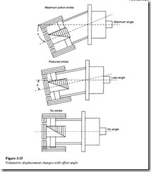
The volumetric displacement of the pump varies with the offset angle ‘B‘. There is no flow when the cylinder block centerline is parallel to the drive shaft centerline. ‘B’ can vary from 0° to 30°. Fixed displacement units are usually provided with 23° or 30° offset angles.
Variable displacement units are provided with a yoke and an external control mechanism to change the offset angle. Some designs have controls which are capable of moving the yoke over the center position to reverse the direction of flow through the pump.
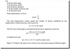
The following nomenclature and analysis are applicable to an axial piston pump:
Let
Swash plate inline piston pump
In this type, the axial reciprocating motion of the pistons is obtained by a swash plate that is either fixed or variable in its degree of angle. As the piston barrel assembly rotates, the pistons rotate around the shaft, with the piston shoes in contact with and sliding along the swash plate surface. Since there is no reciprocating motion when the swash plate is in vertical position, no displacement occurs. As there is an increase in the swash plate angle, the pistons move in and out of the barrel as they follow the angle of the swash plate surface. The pistons move out of the cylinder barrel during one half of the cycle of rotation thereby generating an increasing volume, while during the other half of the rotating cycle, the pistons move into the cylinder barrel generating a decreasing volume. This reciprocating motion results in the drawing in and pumping out of the fluid. Pump capacity can easily be controlled by altering the swash plate angle, larger the angle, greater being the pump capacity. The swash plate angle can easily be controlled remotely with the help of a separate hydraulic cylinder. A cross-sectional view of this pump is shown in Figure 3.16.
The cylinder block and the drive shaft in this pump are located on the same centerline. The pistons are connected through shoes and a shoe plate that bears against the swash plate. As the cylinder rotates, the pistons reciprocate due to the piston shoes following the angled surface of the swash plate. This operation of drawing in and drawing out of the fluid is illustrated in the Figure 3.17.
The outlet and the inlet ports are located in the valve plate so that the pistons pass the inlet as they are being pulled out and pass the outlet as they are being forced back in.
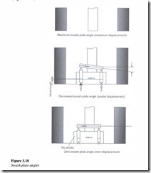
These types of pumps can also be designed to have a variable displacement capability. In such a design, the swash plate is mounted in a movable yoke. The swash plate angle can be changed by pivoting the yoke on pintles.
The positioning of the yoke can be accomplished by manual operation, servo control or a compressor control and the maximum swash plate angle is usually limited to 17.5° (Figure 3.18).
Radial piston pump
These piston pump types have pistons aligned radially on the cylinder block. The operation and construction of a radial piston pump is illustrated in Figure 3.19.
Pump design and operation
The pump consists of a pintle to direct fluid in and out of the cylinder, a cylinder barrel with pistons and a rotor containing a reaction ring. The pistons are placed in radial bores around the rotor. The piston shoes ride on an eccentric ring which causes them to reciprocate as they rotate. The pistons are connected to the inlet port just as they start extending and to the outlet port as they start retracting, by a timed porting arrangement in
the pintle. This action is analogous to the brushes and commutator arrangement in a generator. The pistons remain in constant contact with the reaction ring due to the centrifugal force and the back pressure on the pistons.
For initiating a pumping action, the reaction ring is moved eccentrically with respect to the pintle or shaft axis. As the cylinder barrel rotates, the pistons on one side travel outward. This draws in fluid as each cylinder passes the suction port of the pintle. When the piston passes the maximum point of eccentricity, it is forced inwards by the reaction ring. This forces the fluid to enter the discharge port of the pintle. In certain models, the displacement can be varied by moving the reaction ring to change the piston stroke.


