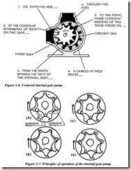
Centered Internal Gear
Another design of internal gear pump is illustrated in Figures 3-6 and 3-7. This pump consists of a pair of gear-shaped elements, one within the other, located in the pump chamber. The inner gear is connected to the drive shaft of the power source.
The operation of this type of internal gear pump is illustrated in Figure 3-7. To simplify the explanation, the teeth of the inner gear and the space between teeth of the outer gear are numbered. Note that the inner gear has one tooth fewer than the outer gear. The tooth forms of the two gears are related in such a way that each tooth of the inner gear is always in sliding contact with the surface of the outer gear. Each tooth of the inner gear meshes with the outer gear at just one point during each revolution. In the illustration, this point is at the (X). In view A, tooth 1 of the inner gear is meshed with space 1 of the outer gear. As the gears continue to rotate in a clockwise direction
and the teeth approach point X, tooth 6 of the inner gear will mesh with space 7 of the outer gear, tooth 5 with space 6, and so on. During this revolution, tooth 1 will mesh with space 2; and during the following revolution with space 3. As a result, the outer gear will rotate at just six-sevenths the speed of the inner gear.
At one side of the point of mesh, pockets of increasing size are formed as the gears rotate, while on the other side the pockets decrease in size. InFigure 3-7, the pockets on the right hand side of the drawings are increasing in size toward the bottom of the illustration, while those on the left-hand side are decreasing in size toward the top of the illustration. The intake side of the pump would therefore be on the right and the discharge side on the left. In Figure 3-7, since the right-hand side of the drawing was turned over to show the ports, the intake and discharge appear reversed .Actually, A in one drawing covers A in the other.
Lobe Pumps
The lobe pump uses the same principles of operation as the external gear pump. The lobes are considerably larger than gear teeth, but there are only two or three lobes on each rotor.A three-lobed pump is illustrated in Figure 3-8. The two elements are rotated, one directly driven by the power source, and the other through timing gears. As the ele ments rotate, liquid is trapped between two lobes of each rotor and the walls of the pump chamber. The trapped liquid is carried from the suction side to the discharge side of the pump chamber. As liquid leaves the suction chamber, the pressure in the suction chamber is lowered and additional liquid is pulled into the chamber from the reservoir.
The lobes are constructed so there is a continuous seal at the points where the two lobes meet at the center of the pump. The lobes of the pump illustrated in Figure 3-8 are fitted with small vanes at the outer edge to improve the seal of the pump . Although these vanes are mechanically held in their slots, they are free to move outward. Centrifugal force keeps the vanes snug against the chamber and the other rotating members.
