Piston pumps
A piston pump is superficially similar to a motor car engine, and a simple single cylinder arrangement was shown earlier in Figure 2.2b. Such a simple pump, however, delivering a single pulse of fluid per revolution, generates unaccept- ably large pressure pulses into the system. Practical piston pumps therefore employ multiple cylinders and pistons to smooth out fluid delivery, and much ingenuity goes into designing multicylinder pumps which are surprisingly compact.
The displacement of a piston pump can be easily calculated:
Q = (number of pistons) × (piston area) × (piston stroke) × (drive speed)
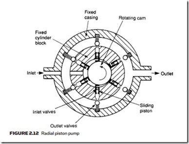
Figure 2.12 shows one form of radial piston pump. The pump consists of several hollow pistons inside a stationary cylinder block. Each piston has spring- loaded inlet and outlet valves. As the inner cam rotates, fluid is transferred rela- tively smoothly from inlet port to the outlet port.
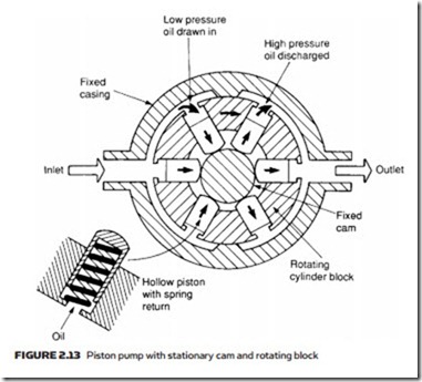
The pump of Figure 2.13 uses the same principle, but employs a stationary cam and a rotating cylinder block. This arrangement does not require multiple inlet and outlet valves and is consequently simpler, more reliable, and cheaper. Not surprisingly most radial piston pumps have this construction. Like gear and vane pumps, radial piston pumps can provide increased displacement by the use of multiple assemblies driven from a common shaft.
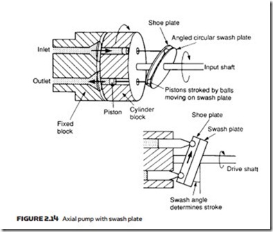
An alternative form of piston pump is the axial design of Figure 2.14, where multiple pistons are arranged in a rotating cylinder. The pistons are stroked by a fixed angled plate called the swash plate. Each piston can be kept in contact with the swash plate by springs or by a rotating shoe plate linked to the swash plate.
Pump displacement is controlled by altering the angle of the swash plate; the larger the angle, the greater the displacement. With the swash plate vertical displacement is zero, and flow can even be reversed. Swash plate angle (and hence pump displacement) can easily be controlled remotely with the addition of a separate hydraulic cylinder.
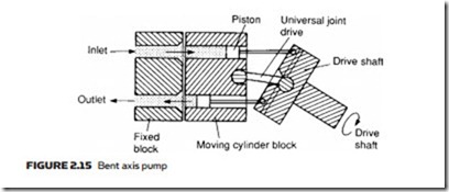
An alternative form of axial piston pump is the bent axis pump of Figure 2.15. Stroking of the pistons is achieved because of the angle between the drive shaft and the rotating cylinder block. Pump displacement can be adjusted by altering the drive shaft angle.
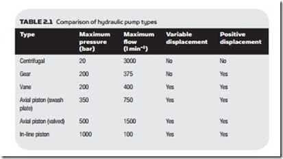
Piston pumps have very high volumetric efficiency (over 98%) and can be used at the highest hydraulic pressures. They are, though, bulky and noisy. Being more complex than vane and gear pumps, they are correspondingly more expensive and maintenance requires more skill. Table 2.1 gives a comparison of the various types of pump.
The figures in Table 2.1 are typical values and manufacturers’ catalogs should be checked for a specific application. The displacement of gear, vane and radial piston pumps can be increased with multiple assemblies. Special- ist pumps are available for pressures up to about 7000 bar at low flows. The
delivery from centrifugal and gear pumps can be made variable by changing the speed of the pump motor with a variable frequency (VF) drive.
