TURBULENT FLOW IN TUBES
We mentioned in Chap. 14 that flow in smooth tubes is fully turbulent for Re > 4000. Turbulent flow is commonly utilized in practice because of the higher heat transfer coefficients associated with it. Most correlations for the friction and heat transfer coefficients in turbulent flow are based on experimental studies because of the difficulty in dealing with turbulent flow theoretically.
For smooth tubes, the friction factor in turbulent flow can be determined from the explicit first Petukhov equation [Petukhov (1970)] given as
Once the friction factor is available, this equation can be used conveniently to evaluate the Nusselt number for both smooth and rough tubes.
For fully developed turbulent flow in smooth tubes, a simple relation for the Nusselt number can be obtained by substituting the simple power law relation f = 0.184 Re-0.2 for the friction factor into Eq. 19–77. It gives
which is known as the Colburn equation. The accuracy of this equation can be improved by modifying it as where n = 0.4 for heating and 0.3 for cooling of the fluid flowing through the tube. This equation is known as the Dittus–Boelter equation [Dittus and Boelter (1930)] and it is preferred to the Colburn equation.
The fluid properties are evaluated at the bulk mean fluid temperature Tb = (Ti + Te)/2. When the temperature difference between the fluid and the wall is very large, it may be necessary to use a correction factor to account for the different viscosities near the wall and at the tube center.
The Nusselt number relations above are fairly simple, but they may give errors as large as 25 percent. This error can be reduced considerably to less than 10 percent by using more complex but accurate relations such as the sec- ond Petukhov equation expressed as
where the friction factor f can be determined from an appropriate relation such as the first Petukhov equation. Gnielinski’s equation should be preferred in calculations. Again properties should be evaluated at the bulk mean fluid temperature.
The relations above are not very sensitive to the thermal conditions at the tube surfaces and can be used for both T = constant and · = constant cases.
Despite their simplicity, the correlations already presented give sufficiently accurate results for most engineering purposes. They can also be used to obtain rough estimates of the friction factor and the heat transfer coefficients in the transition region 2300 :s Re :s 4000, especially when the Reynolds number is closer to 4000 than it is to 2300.
The relations given so far do not apply to liquid metals because of their very low Prandtl numbers. For liquid metals (0.004 < Pr < 0.01), the following relations are recommended by Sleicher and Rouse (1975) for 104 < Re < 106:
where the subscript s indicates that the Prandtl number is to be evaluated at the surface temperature.
In turbulent flow, wall roughness increases the heat transfer coefficient h by a factor of 2 or more [Dipprey and Sabersky (1963)]. The convection heat transfer coefficient for rough tubes can be calculated approximately from the Nusselt number relations such as Eq. 19–81 by using the friction factor determined from the Moody chart or the Colebrook equation. However, this approach is not very accurate since there is no further increase in h with f for f > 4fsmooth [Norris (1970)] and correlations developed specifically for rough tubes should be used when more accuracy is desired.
Developing Turbulent Flow in the Entrance Region
The entry lengths for turbulent flow are typically short, often just 10 tube diameters long, and thus the Nusselt number determined for fully developed turbulent flow can be used approximately for the entire tube. This simple approach gives reasonable results for pressure drop and heat transfer for long tubes and conservative results for short ones. Correlations for the friction and heat transfer coefficients for the entrance regions are available in the literature for better accuracy.
Turbulent Flow in Noncircular Tubes
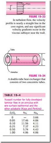
The velocity and temperature profiles in turbulent flow are nearly straight lines in the core region, and any significant velocity and temperature gradients occur in the viscous sublayer (Fig. 19–33). Despite the small thickness of laminar sublayer (usually much less than 1 percent of the pipe diameter), the characteristics of the flow in this layer are very important since they set the stage for flow in the rest of the pipe. Therefore, pressure drop and heat transfer characteristics of turbulent flow in tubes are dominated by the very thin viscous sublayer next to the wall surface, and the shape of the core region is not of much significance. Consequently, the turbulent flow relations given above for circular tubes can also be used for noncircular tubes with reasonable accuracy by replacing the diameter D in the evaluation of the Reynolds number by the hydraulic diameter Dh = 4Ac /p.
Flow through Tube Annulus
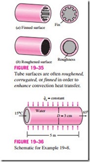
Some simple heat transfer equipments consist of two concentric tubes, and are properly called double-tube heat exchangers (Fig. 19–34). In such devices, one fluid flows through the tube while the other flows through the annular space. The governing differential equations for both flows are identical. Therefore, steady laminar flow through an annulus can be studied analytically by using suitable boundary conditions.
Consider a concentric annulus of inner diameter Di and outer diameter Do. The hydraulic diameter of annulus is
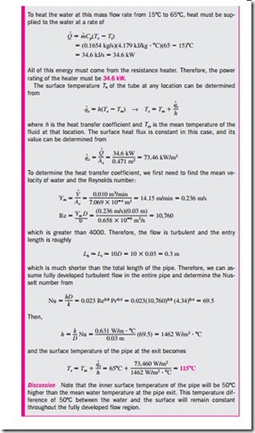
Annular flow is associated with two Nusselt numbers—Nui on the inner tube surface and Nuo on the outer tube surface—since it may involve heat transfer on both surfaces. The Nusselt numbers for fully developed laminar flow with one surface isothermal and the other adiabatic are given in Table 19–4. When Nusselt numbers are known, the convection coefficients for the inner and the outer surfaces are determined from
For fully developed turbulent flow, the inner and outer convection coefficients are approximately equal to each other, and the tube annulus can be treated as a noncircular duct with a hydraulic diameter of Dh = Do – Di. The Nusselt number in this case can be determined from a suitable turbulent flow relation such as the Gnielinski equation. To improve the accuracy of Nusselt numbers obtained from these relations for annular flow, Petukhov and Roizen (1964) recommend multiplying them by the following correction factors when one of the tube walls is adiabatic and heat transfer is through the other wall:
Heat Transfer Enhancement
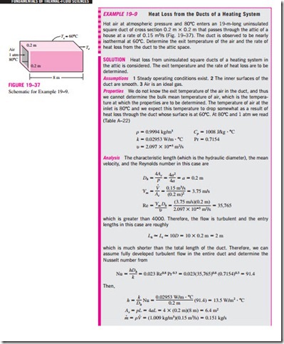
Tubes with rough surfaces have much higher heat transfer coefficients than tubes with smooth surfaces. Therefore, tube surfaces are often intentionally roughened, corrugated, or finned in order to enhance the convection heat transfer coefficient and thus the convection heat transfer rate (Fig. 19–35). Heat transfer in turbulent flow in a tube has been increased by as much as 400 percent by roughening the surface. Roughening the surface, of course, also increases the friction factor and thus the power requirement for the pump or the fan.
