Working relationships
With the set of three derived relationships that can be considered to be reasonably precise, and two empirical relationships, some straightforward relationships can be
obtained that can be used for providing a quick check on a system design or on the operation of an existing system.
Material flow rate
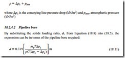
By directly equating Equations (18.1) and (18.8) and re-arranging, an expression for material flow rate is derived:
Pipeline inlet conditions are the most convenient to use here.
Negative pressure systems
For vacuum systems the pressure, p, will be atmospheric.
Positive pressure systems
For positive pressure systems the pressure, p, in Equation (18.10) will be equal to the conveying line pressure drop, !lpc, plus atmospheric pressure. This is:
The situation for both positive and negative pressure systems is the same as above.
Air supply pressure
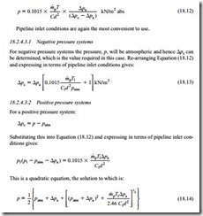
Alternatively, the expression can be in terms of the pressure required to convey the material. Substituting the solids loading ratio, </, from Equation (18.8) into (18.6) gives:
Note: This will give the correct root.
Air only pressure drop
Since the air only pressure drop, !lpa, features prominently in these models, a conven- ient expression for this pressure drop is required. An expression that will give the air only pressure drop in terms of conveying line inlet, or exit, air velocity is needed.
Negative pressure systems
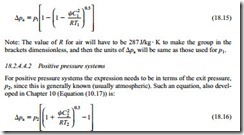
For negative pressure systems the expression also needs to be in terms of the inlet air pressure, p1, since this is generally known (usually atmospheric). Such an equation was developed in Chapter 10 (Equation (10.20)) and is:
Note that R must have units of J/kg · K as in Equation (18.15) above.
Vertical conveying
The models presented so far relate essentially to horizontal pipelines. Most pneumatic conveying systems, however, will include a vertical lift and so this needs to be taken into account. The pressure drop in vertical conveying over a very wide range of solids loading ratio values, is approximately double that for horizontal conveying, as consid- ered in Chapter 14. Sections of vertical conveying in a pipeline, therefore, can most conveniently be accounted for by working in terms of an equivalent length and allow- ing double for vertical lifts. This equivalent length replaces the actual pipeline length in Equation (10.2) and subsequent equations.
Procedure
To illustrate the process it is proposed to investigate the possibility of conveying a coarse material at a flow rate, m· p1, of 30 tonne/h using a positive displacement blower and a positive pressure conveying system. The pipeline is 135 m long, with 110 m horizontal and 25 m vertical lift, giving an equivalent length, Le, of 160 m, plus five 90° bends. It is assumed that the temperature of the air and material at the conveying line inlet, T1, are 300 K (27°C).
In the first instance the possibility of conveying the material in a 200 mm bore pipeline, d1, is to be investigated. Since the material can only be conveyed in dilute phase suspension flow a conveying line inlet air velocity, C1, of 17 m/s is taken.
Air only pressure drop
The starting point in the process is to evaluate the air only pressure drop, !lpa, for the pipeline and potential conveying parameters. Details of the pipeline are specified but those for the conveying parameters will not be known until the calculation is com- pleted, and so assumptions will need to be made in order to get the process started. If, at the end of the calculation the assumptions made are too far removed from the values calculated, the process will have to be repeated, and hence it is an iterative solution.
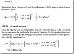
Possibly the best equation for the air only pressure drop for the given situation is Equation (18.16) presented above. The conveying line outlet air velocity, C2, is the only unknown here and so a value has to be estimated. If it is estimated that the conveying line pressure drop will be about 0.75 bar, then C2 will approximately equal 1.75 X C1, and as C1 is 17 m/s, as specified earlier, then C2 will be approximately 30 m/s.
The pipeline friction loss coefficient was presented in Chapter 10:
This was Equation (10.11). Taking a bend loss coefficient of 0.2 (Figure 10.6) for each of the five bends, and a pipeline exit loss coefficient of 1.0 (Figure 10.10), gives a value of ‘i,k = 2. Substituting a pipeline friction coefficient f = 0.0045, the equivalent length of 160 m and the pipeline bore of 0.2 m gives:
Since this value is lower and very close to that of the original estimate then a 200 mm bore pipeline would appear to be appropriate for the duty.

