FLOW WORK AND THE ENERGY OF A FLOWING FLUID
Unlike closed systems, control volumes involve mass flow across their boundaries, and some work is required to push the mass into or out of the control volume. This work is known as the flow work, or flow energy, and is necessary for maintaining a continuous flow through a control volume.
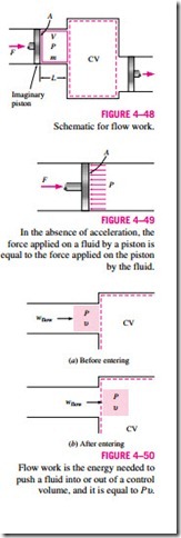
To obtain a relation for flow work, consider a fluid element of volume V as shown in Fig. 4–48. The fluid immediately upstream will force this fluid element to enter the control volume; thus, it can be regarded as an imaginary piston. The fluid element can be chosen to be sufficiently small so that it has uniform properties throughout.
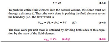
If the fluid pressure is P and the cross-sectional area of the fluid element piston is
The flow work relation is the same whether the fluid is pushed into or out of the control volume (Fig. 4–50).
It is interesting that unlike other work quantities, flow work is expressed in terms of properties. In fact, it is the product of two properties of the fluid. For that reason, some people view it as a combination property (like enthalpy) and refer to it as flow energy, convected energy, or transport energy instead of flow work. Others, however, argue rightfully that the product Pυ represents energy for flowing fluids only and does not represent any form of energy for nonflow (closed) systems. Therefore, it should be treated as work. This controversy is not likely to end, but it is comforting to know that both arguments yield the same result for the energy equation. In the discussions that follow, we consider the flow energy to be part of the energy of a flowing fluid, since this greatly simplifies the energy analysis of control volumes.
Total Energy of a Flowing Fluid
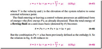
As we discussed in Chap. 1, the total energy of a simple compressible system consists of three parts: internal, kinetic, and potential energies (Fig. 4–51). On a unit-mass basis, it is expressed as
By using the enthalpy instead of the internal energy to represent the energy of a flowing fluid, one does not need to be concerned about the flow work. The energy associated with pushing the fluid into or out of the control volume is automatically taken care of by enthalpy. In fact, this is the main reason for defining the property enthalpy. From now on, the energy of a fluid stream flowing into or out of a control volume is represented by Eq. 4–49, and no reference will be made to flow work or flow energy.
Energy Transport by Mass
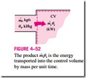
Noting that u is total energy per unit mass, the total energy of a flowing fluid of mass m is simply m u, provided that the properties of the mass m are uniform. Also, when a fluid stream with uniform properties is flowing at a mass flow rate of m· , the rate of energy flow with that stream is m· u (Fig. 4–52). That is,
When the kinetic and potential energies of a fluid stream are negligible, as is usually the case, these relations simplify to E = mh and · = m· h.
In general, the total energy transported by mass into or out of the control volume is not easy to determine since the properties of the mass at each inlet or exit may be changing with time as well as over the cross section. Thus, the only way to determine the energy transport through an opening as a result of mass flow is to consider sufficiently small differential masses dm that have uniform properties and to add their total energies during flow.
Again noting that u is total energy per unit mass, the total energy of a flow- ing fluid of mass dm is u dm. Then the total energy transported by mass through an inlet or exit (miui and meue) is obtained by integration. At an inlet, for example, it becomes
Most flows encountered in practice can be approximated as being steady and one-dimensional, and thus the simple relations in Eqs. 4–50 and 4–51 can be used to represent the energy transported by a fluid stream.
