COUNTERBALANCED VALVES
The counterbalance valve is normally located in the line between a directional control valve and the outlet of a vertical mounted actuating cylinder that supports weight or must be held in position for a period of time. This valve serves as a hydraulic resis tance to the actuating cylinder. For example, counterbalance valves are used in some hydraulically operated forklifts. The valve offers a resistance to the flow from the actuating cylinder when the fork is lowered. It also helps to support the fork in the UP position.
One type of counterbalance valve is illustrated in Figure 7-17. The valve element is a balanced spool (4). The spool consists of two pistons permanently fixed on either end of a shaft. The inner surface areas of the pistons are equal. Therefore, pressure acts equally on both areas regardless of the position of the valve and has no effect on the movement of the valve. The shaft area between the two pistons provides the area for the fluid to flow when the valve is open. A small piston (9) is attached to the bottom of the spool valve.
When the valve is in the closed position, the top piston of the spool blocks the dis charge port (8). With the valve in this position, fluid flowing from the actuating unit enters the inlet port (5). The fluid cannot flow through the valve because the discharge port (8) is blocked. However, fluid will flow through the pilot passage (6) to the small pilot piston. As the pressure increases, it acts on the pilot piston until it overcomes the preset pressure of spring 3.
This forces the valve spool (4) up and allows the fluid to flow around the shaft of the valve spool and out discharge port 8. Figure 7-17 shows the valve in this position. During reverse flow, the fluid enters port 8. The spring (3) forces valve spool4 to the closed posi tion. The fluid pressure overcomes the spring tension of check valve 7. The check valve opens and allows free flow around the shaft of the valve spool and out through port 5.
The operating pressure of the valve can be adjusted by turning the adjustment screw ( 1), which increases or decreases the tension of the spring. This adjustment depends on the weight that the valve must support. It is normal for a small amount of fluid to leak around the top piston of the spool valve and into the area around the spring. An accumulation would cause additional pressure on top of the spool valve. This would require additional pressure to open the valve. The drain (2) provides a passage for this fluid to flow to port 8.
DIRECTIONAL CONTROL VALVES
Directional control valves are designed to direct the flow of fluid, at the desired time, to the point in a fluid power system where it will do work. The driving of a ram back and forth in its cylinder is an example of when a directional control valve is used. Var ious other terms are used to identify directional valves, such as selector valve, transfer valve, and control valve. This manual will use the term directional control valve to identify these valves.
Directional control valves for hydraulic and pneumatic systems are similar in design and operation. However, there is one major difference. The return port of a hydraulic valve is ported through a return line to the reservoir. Any other differences are pointed out in the discussion of these valves.
Directional control valves may be operated by differences in pressure acting on oppo site sides of the valve elements, or they may be positioned manually, mechanically, or electrically. Often two or more methods of operating the same valve will be used in different phases of its action.
Directional control valves can be classified in several ways: by the type of control, the number of ports in the valve housing, and the specific function that the valve per forms. The most common method is by the type of valving element used in the con struction of the valve. The most common types of valving elements are the ball, cone, sleeve, poppet, rotary spool, and sliding spool. The basic operating principles of the poppet, rotary spool, and sliding spool types are discussed in this text.
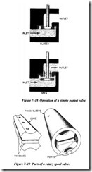
The poppet fits into the center bore of the seat (Figure 7-18). The seating surfaces of the poppet and the seat are lapped or closely machined so that the center bore will be sealed when the poppet is seated (shut). The action of the poppet is similar to that of the valves in an automobile engine. In most valves the poppet is held in the seated position by a spring.
The valve consists primarily of a movable poppet, which closes against the valve seat. In the closed position, fluid pressure on the inlet side tends to hold the valve tightly
closed. A small amount of movement from a force applied to the top of the poppet stem opens the poppet and allows fluid to flow through the valve.
The rotary spool directional control valve (Figure 7-19) has a round core with one or more passages or recesses in it. The core is mounted within a stationary sleeve. As the core is rotated within the stationary sleeve, the passages or recesses connect or block the ports in the sleeve. The ports in the sleeve are connected to the appropriate lines of the fluid system.
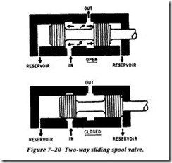
The operation of a simple sliding spool directional control valve is shown in Figure 7-20. The valve is so named because of the shape of the valving element that slides back and forth to block or open ports in the valve housing. The sliding element is referred to as the spool or piston. The inner piston areas, or lands, are equal. Thus, fluid under pressure, which enters the valve from the inlet, ports acts equally on both inner piston areas, regardless of the position of the spool. Sealing is usually accomplished by a very closely machined fit between the spool and the valve body or sleeve. For valves with more ports, the spool is designed with more pistons or lands on a common shaft. The sliding spool is the most common type of directional control valve.
CHECK VALVES
Check valves are used in fluid systems to permit flow in one direction and to prevent flow in the opposite direction. They are classified as one-way directional control valves. The check valve may be installed independently in a line to allow one-direc tion flow, or it may be used as an integral part of globe, sequence, counterbalance, and pressure-reducing valves.
Check valves are available in various designs. They are opened by the force of fluid in motion flowing in one direction, and are closed by fluid attempting to flow in the opposite direction. The force of gravity or the action of a spring aids in closing the valve.
Figure 7-21 shows a swing check valve. In the open position, the flow of fluid forces the hinged disc up and allows free flow through the valve. Flow in the opposite direc tion, or loss of flow, with the aid of gravity forces the hinged disc to close the passage
and blocks the flow. This type of valve is sometimes designed with a spring to assist in closing the valve.
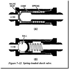
The most common type of check valve uses either a ball or cone for the sealing ele ment (Figure 7-22). As fluid pressure is applied in the direction of the arrow (flow), the cone (view A) or ball (view B) is forced off its seat, allowing fluid to flow freely through the valve. This valve is known as a spring-loaded check valve.
The spring is installed in the valve to hold the cone or ball on its seat whenever fluid is not flowing. The spring also helps to force the cone or ball on its seat when the fluid attempts to flow in the opposite direction. Since the opening and closing of this type of valve are not dependent on gravity, its location in a system is not limited to the ver tical position.
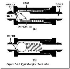
A modification of the spring-loaded check valve is the orifice check valve (Figure 7- 23A,B). This valve allows normal flow in one direction and restricted flow in the opposite direction. It is referred to as a one-way restrictor.
Figure 7-23, view A, shows a cone-type orifice check valve. When sufficient fluid pressure is applied at the inlet port, it overcomes spring tension and moves the cone off of its seat. The two orifices (2) in the illustration represent several openings located around the slanted circumference of the cone. These orifices allow free flow of fluid through the valve while the cone is off its seat. When fluid pressure is applied through the outlet port, the force of the fluid and spring tension move the cone to the left and onto its seat. This action blocks the flow of fluid though the valve, except through the orifice ( 1) in the center of the cone. The size of the orifice determines the rate of flow through the valve as the fluid flows from right to left.


