Liquid Seal Ring Compressors
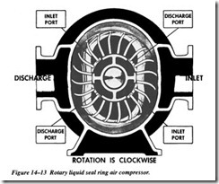
The rotary liquid seal ring type, as illustrated in Figure 14-13, features a forward inclined, open impeller in an oblong cavity filled with liquid. As the impeller rotates, the centrifugal force causes the seal liquid to collect at the outer edge of the oblong cavity. Because of the oblong configuration of the compressor case, large longitudinal cells are created and reduced to smaller ones. The suction port is positioned where the longitudinal cells are the largest, and the discharge port where they are smallest, thus causing the vapor within the cell to compress as the rotor rotates. The rotary liquid seal compressor is frequently used in specialized applications for the compression of extremely corrosive and exothermic gases and is commonly used in commercial nuclear plants as a means of establishing initial condenser vacuum.
The rotary liquid-piston or liquid-ring compressor uses a rotor with multiple forward turned blades turning about a central cone containing inlet and discharge ports. The blades drive a captive ring of liquid around the inside of an elliptical casing. The basic elements are the casing heads and rotor assembly.
A certain amount of liquid is trapped between adjacent blades, and as the rotor turns, the liquid face moves in and out of this space because of the casing shape. This cre ates a liquid piston. Porting in the central cone is built-in and fixed. There are no valves.
There is compression within the pockets or chambers between the blades before the discharge port is uncovered. Since the port location must be designed and built for a specific compression ratio, it will tend to operate above or below the design pressure.
The cooling of liquid-ring compressors is direct rather than through the walls of the casing. The required additional cooling liquid is fed into the casing where it comes into direct contact with the gas being compressed. The excess liquid is discharged with the gas. The discharged mixture is passed through a conventional baffle or cen trifugal type separator to remove the free liquid. Because of the intimate contact of gas and liquid, the final discharge temperature can be held close to the temperature of the inlet cooling water. However, the discharge gas is saturated at the discharge tem perature of the compressed liquid.
The amount of liquid that may be passed through the compressor is not critical and can be varied to obtain the desired results. The unit will not be damaged if a large quantity of liquid inadvertently enters its suction. Lubrication is required only in the bearings, which are generally located external to the casing. The liquid itself acts as a lubricant, sealing medium, and coolant for the stuffing boxes.
Dynamics and Failure Modes
The liquid-ring compressor operates much like any rotation machine train. It will gen erate the same dynamics and vibration profile as a centrifugal pump or fan. Although the compressor is positive displacement, i.e., discharges the same volume for each rotation, its operating dynamics are centrifugal.
DYNAMIC (CENTRIFUGAL) COMPRESSORS
Compression in any dynamic or centrifugal compressor depends on the transfer of energy from a rotating set of blades to a gas. The rotor accomplishes this energy trans fer by changing the momentum and pressure of the gas. The momentum, i.e., kinetic energy, then is converted into useful pressure energy by slowing the gas down in a sta tionary diffuser or another set of blades. Dynamic compressors are generally designated as centrifugal, axial, or mixed-flow. Although these compressors are con structed differently, the same basic aerodynamic design theory applies to all three.
Centrifugal Compressors
The centrifugal designation is used when the gas flow is radial and the energy transfer is predominantly due to a change in the centrifugal forces acting on the gas.
The centrifugal compressor, originally built to handle only large volumes of low-pres sure gas and air (maximum of 40 psig), has been developed to enable it to move large volumes of gas with discharge pressures up to 3,500 psig. However, centrifugal com pressors are now most frequently used for medium-volume and medium-pressure air delivery. One advantage of a centrifugal pump is the smooth discharge of the com pressed air.
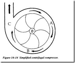
The centrifugal force utilized by the centrifugal pump is the same force utilized by the centrifugal compressors. The air particles enter the eye of the impeller, designated D in Figure 14-14. As the impeller rotates, air is thrown against the casing of the com pressor. The air becomes compressed as more and more air is thrown out to the casing by the impeller blades. The air is pushed along the path designated A, B, and C in Fig ure 14-14. The pressure of the air is increased as it is pushed along this path.
There may be several stages to a centrifugal air compressor, as in the centrifugal pump, and the result would be the same; a higher pressure would be produced. The air compressor is used to create compressed or high-pressure air for a variety of uses. Some of its uses are pneumatic control devices, pneumatic sensors, pneumatic valve operators, pneumatic motors, and starting air for diesel engines.
Design Considerations
The centrifugal compressor has a limited stable operating range. This may affect the economics of operation at partial load. The minimum capacity may vary from 45 to 90 percent of rated capacity. The centrifugal must be selected for the worst combination of conditions that exist at a givec time and must be controlled to meet other requirements.
Operating speeds are high compared to other compressors. Speeds between 50,000 and 100,000 rpm are common in some compressor designs. For example, the fourth stage impeller in a typical bullgear-type compressor, such as the Ingersoll-Rand Cen tac (Figure 14-15), will normally operate above 60,000 rpm.
These compressors are well suited for direct connection to steam or gas turbine drivers, which permit variable speed control. Variable speed control is the only recommended means of volume or load control on centrifugal compressors. They are designed to be base-loaded and to operate continuously at constant volume and pressure.
In normal operating conditions, i.e., base-loaded, these machines have a high avail ability factor. They frequently operate without shutdown for 2 to 3 years.
Dynamics and Failure Modes
The dynamics of a centrifugal compressor are the same as for other centrifugal machine trains. The dominant forces and vibration profiles will be identical to those of a pump or fan. However, the effects of variable load and other process variables, such as temperature and inlet/discharge pressure, are more pronounced than in other rotating machines.
Monitoring and diagnostic techniques and methods should be the same as for a similar pump, gearbox, or other similar rotating machine train. Radial measurements
should be located in the planes that will provide the earliest indication of shaft dis placement created by abnormal operation.
Aerodynamic instability is the most common failure mode of centrifugal compressors. Variable demand or restrictions of the inlet airflow are the more common sources of this instability. Even slight variations in either of these process variables can result in dramatic changes in the operating stability of the compressor.
Entrained liquid and solids can also affect operating life of centrifugal compressors. Controlled liquid injection for cooling and cleaning may be considered in design. When dirty air must be handled, open-type impellers must be used. Their open design will permit the capability to handle a moderate amount of dirty or other solids in the inlet air supply. However, inlet filters are recommended for all applications.
The actual dynamics of centrifugal compressors is driven by their design. A variety of designs ranging from overhung rotors to bullgears are commonly used:
Overhung or cantilever. The cantilever design is more susceptible to pro cess instability than centerline compressors. Figure 14-16 illustrates a typ ical cantilever design.
The overhung design of the rotor, i.e., no outboard bearing, increases the potential for radical shaft deflection. Any variation in laminar flow of inlet or discharge air will force the shaft to bend or deflect from its true center line. As a result, mode shape of the shaft must be monitored closely. If there is any indication of deflection, the air control system, i.e., dampers or
flow-control valves, must be inspected and the system balanced to permit stable operation.
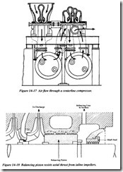
Centerline design. Centerline designs, such as the horizontal and vertical split-case, are more stable over a wider operating range, but should not be operated in a variable-demand system. Figure 14-17 illustrates the normal airflow pattern through a horizontal split-case compressor. Inlet air enters the first stage of the compressor where the pressure and veloc ity are increased. The partially compressed air is routed to the second stage where the velocity is further increased. This process can be contin ued , by adding additional stages, until the final discharge pressure is achieved.
Two factors are critical to the normal operation of these compressors: the fact that laminar flow must be maintained through all stages, and the design of the impeller.
There are two impeller designs used in centrifugal compressors: inline and back-to hack. In the former, all impellers face in the same direction. In the latter, impeller direction is reversed in adjacent stages.
Inline impellers–<::ompressors with all impellers facing in the same direction-will, by design, generate substantial axial forces. The axial pressure generated by each impeller will be added for all stages, and as a result massive axial loads will be trans mitted to the fixed bearing. Thus, most of these compressors will use either a Kings bury thrust bearing or a balancing piston to resist this axial thrusting. Figure 14-18 illustrates a typical balancing piston.
All compressors that use inline impellers must be monitored closely for axial thrust ing. If the compressor is subjected to frequent or constant unloading, the axial clear ance will be increased. Ultimately, this will lead to catastrophic failure of the compressor.
Opposed impellers are a different matter. Reversing the direction of alternating impel lers means that the axial forces generated by each impeller can be minimized by opposing force of the adjacent impeller. In effect, the opposed impellers tend to can cel the axial forces generated by the preceding stage.
This design is more stable and should not generate measurable axial thrusting. There fore, these units contain a normal float and fixed rolling-element bearing.


