COMPRESSORS
COMMON COMPONENTS
A compressor must operate within a system that is designed to acquire and compress a gas. These systems must include certain components, regardless of compressor type.
Lubrication System
The lubrication system has two basic functions: to lubricate the compressor’s moving components and to cool the system by removing heat from the compressor’s moving parts. Although all compressors must have a lubrication system, the actual design and function of these systems will vary depending on compressor type.
Centrifugal Compressors
The lubricating system for centrifugal or dynamic compressors is designed to provide bearing lubrication. In smaller compressors, the lubrication systems may consist of individual oil baths located at each of the main shaft bearings. In larger compressors, such as a bullgear design, a positive system is provided to inject oil into the internal, tilting-pad bearings located at each of the pinion shafts inside the main compressor housing.
In positive lubrication systems, a gear-type pump is normally used to provide positive circulation of clean oil within the compressor. In some cases, the main compressor shaft directly drives this pump. In others, a separate motor-driven pump is used.
Positive-Displacement Compressors
Positive-displacement compressors use their lubrication system to provide additional functions. The lubrication system must inject sufficient quantities of clean fluid to provide lubrication for the compressor’s internal parts, such as pistons and lobes, and to provide a positive seal between moving and stationary parts.
The main components of a positive-displacement compressor’s lubrication system consist of an oil pump, filter, and heat exchanger. The crankcase of the compressor acts as the oil sump. A lockable drain cock is installed at the lowest end of the crank case to permit removal of any water accumulation that has resulted from sweating of the crankcase walls. The oil passes through a strainer into the pump. It then flows through the heat exchanger, where it is cooled. After the heat exchanger, the cooled oil flows directly to the moving parts of the compressor before returning to the crank case sump. A small portion is diverted to the oil injector, if one is installed. The oil that is injected into the cylinder seals the space between the cylinder wall and the pis ton rings. This prevents compressed air from leaking past the pistons, and thus improves the compressor’s overall efficiency.
Lube Pump
The oil pump is usually gear driven from the crankshaft so that it will start pumping oil immediately on startup of the compressor. In compressors that work in an oil-free system, oil injectors are not used. Oil separators are installed on the discharge side after leaving the aftercooler.
Oil Separator
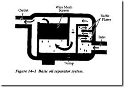
The basic purpose of an oil separator is to clean the pressurized air of any oil contam ination, which is highly detrimental to pneumatically controlled instrumentation. A separator consists of an inlet, a series of internal baffle plates, a wire mesh screen, a sump, and an outlet (Figure 14-1). The pressurized air enters the separator and imme diately passes through the baffle plates. As the air impinges on the baffle plates, it is forced into making sharp directional changes as it passes through each baffle section. As a result, the oil droplets separate from the air and collect on the baffles before dropping into the separator’s sump.
After the air clears the baffle section, it then passes through the wire mesh screen where any remaining oil is trapped.
The relatively oil-free air continues to the air reservoir for storage. The air reservoir acts as a final separator where moisture and oil is eventually removed. The air reservoir has drain traps installed at its lowest point where any accumulated moisture/oil is automatically discharged.
As a part of any routine maintenance procedure, these discharge traps should periodi cally be manually bypassed to ensure that the trap is functioning, and no excessive water accumulation is evident.
POSITIVE-DISPLACEMENT COMPRESSORS
As their name implies, this classification of compressor will displace a constant volume of gas for each complete cycle or rotation of its primary shaft. Unlike centrifugal compressors, a positive-displacement compressor will continue to generate pressure until it exceeds its maximum limits. This design feature can create problems in com pressed-air systems. Systems designed to operate at 100 psig may reach line pressures of 150 psig or more. Therefore, it is imperative that all positive-displacement systems include a positive means of relieving excess pressure.
Normally, compressed air systems that use positive-displacement compressors will include both pressure relief valves and an automatic pressure control system that peri odically unloads the compressor.
There are three basic types of positive-displacement compressors: reciprocating, rotary screw, and vane type. Although the actual configuration and dynamics of these compressors vary, they all share common design concepts.
RECIPROCATING COMPRESSORS
Reciprocating compressors are the most widely used of all compression equipment and also provide the widest range of sizes and types. Ratings vary from fractional to more than 12,000 horsepower units. Pressures range from low vacuums, at intake, to special process compressors for 60,000 psig or higher.
In common with all positive-displacement compressors, the reciprocating type is classified as a constant-volume variable-pressure machine. They are the most efficient type of compressor and can be used in partial loads or reduced capacity applications. Because of the reciprocating pistons and other parts, as well as some unbalanced rotating parts, inertia forces are set up that tend to shake the unit. It is necessary to provide a mounting that will stabilize the installation. The extent of this requirement will depend on the type and size of the compressor.
Reciprocating compressors should be supplied with clean gas. Inlet filters are recom mended in all applications. They cannot satisfactorily handle liquids that may be entrained in the gas, although vapors are no problem if condensation within the cylinders does not take place. Liquids tend to destroy lubrication and cause excessive wear. Recip rocating compressors deliver a pulsating flow of gas. This is sometimes a disadvantage, but pulsation dampers can usually eliminate the problem.
