Tool lubrication
Unless an oil-free compressor has been used, there will be oil contained in the air in the form of droplets or as a vapour. Usually this amount is quite small if the compressor is well maintained and if the oil separation equipment is functioning properly. Unless the air is required for breathing or for process applications, this oil causes no difficulty, but it is insufficient in quantity to lubricate those items of equipment that need a supply of oil for lubrication, and in any case is probably of the wrong type.
All pneumatic tools benefit from having a regular supply of oil fed to them, and the best way of doing this is to inject into the air stream a continuous mist of oil droplets. The ideal properties needed by an oil to lubricate a tool are different from those required to lubricate a compressor. Oil used to lubricate pneumatic tools is, of course, wasted in the exhaust, so regular topping up of the oil supply reservoir is important- a check should be made at least every shift.
Mobile compressors, particularly when used on construction sites incorporate little by way of air treatment. Some suppliers of this kind of compressor supply, as an optional extra, a lubricator mounted on its chassis, but the competitive nature of the business means that this option is rarely used.
An air tool works by expansion of the air working against a piston, vane or gear, and this expansion results in a lowering of the temperature and the condensation of the water vapour in the air. These two effects mean that the lubricating oil used must be capable of
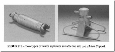
functioning at a low temperature and of resisting the washing effect of the condensate. If the moisture has previously been removed in a filter or separator, the fall in temperature in a tool is unlikely to cause condensation, but in practice most compressed air systems do not include a separator, and the problem of water washing has to be dealt with in the tool itself. It is not necessary with construction site equipment to have an elaborate water separator; one which is specifically designed to be robust enough for site use is a worthwhile investment. Two examples are shown in Figure 1. The in-line type is for a single tool use, with automatic water discharge; the sled mounted type has to be emptied regularly but has a large holding capacity.
Resistance to water washing is embodied in the lubricant by the introduction of chemical-type emulsifying and adhesive agents. These agents enable the oil to combine with the moisture to form emulsions which cling to the lubricated surface and thus act as a barrier to prevent condensation settling on the internal surfaces. In this way rust cannot be formed to impair the movement of the working parts. Tools which are used in mines need special protection, because the water may be highly acidic and corrosion caused by acidic condensate can be very rapid. Ifan oil which has no emulsifying properties is used, the water will wash the film of oil off the working surface, resulting in inadequate lubrication and excessive wear. Straight high quality mineral oils would need to be used in excessive quantities to combat water washing, whereas a correctly formulated oil in minimum quantities would provide adequate protection.
The low temperatures inside a tool demand the use of a lubricant with a low pour point, so that it will be sufficiently fluid to pass through a lubricator and to reach all parts of a tool.
In addition to these two characteristics, there are a number of other properties that a lubricant must possess.
Film strength is a characteristic which determines the ability of an oil to protect the moving parts under high pressure, particularly on the piston splines of a rock drill and on the sliding vanes of a motor.
High lubricity ensures the minimum drag as one component slides over another; this ensures efficient operation.
Correct viscosity in an oil used for piston lubrication is most important. Oils which are too heavy in body tend to slow up valve action and interfere with the tool operation. The correct viscosity oil will also ensure a good seal between the piston and cylinder of a tool. Most tools do not have seals and much air can be wasted through leakage.
Chemical stability is a property which determines an oil’s resistance to oxidation and to the formation of gummy residues. Some percussive tools are prone to “dieselling” (so called because it is similar to what happens in a compression-ignition engine), when the impact energy of the piston is not fully absorbed by the drill stem and the excess is absorbed by compression of the air at the front of the tool, with such a force that auto-ignition takes place. An oil with a low auto-ignition temperature could exacerbate this danger.
The oil should have chemical properties that are non-irritant and not unpleasant in a confined location, such as underground, where ventilation may be inadequate.
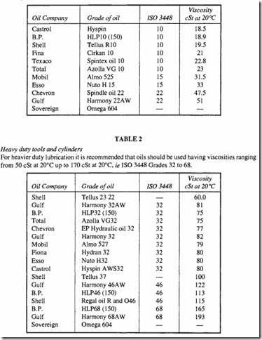
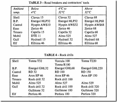
Tables 1 to 4 give a selection of suitable mineral oils with the required properties. Their use will considerably extend the life of tools and other equipment. The recommendations
in the tables are suitable for the purposes indicated, however it should be emphasised that manufacturer’s literature should be referred to for specific information. Suppliers other than those listed also have suitable formulations.
There are also some synthetic formulations based on glycol, which have been developed in conjunction with tool manufacturers with the aim of producing a lubricant which absorbs moisture, has a wide temperature range and decomposes without harm to the environment; these tend to be more expensive than mineral oils but have the advantage that because they are able to absorb larger amounts of water, it may be possible to dispense with the water separator. Care should be taken with the use of these lubricants, making sure that they are suitable for the application envisaged.
The lubrication requirements for small industrial tools and for cylinders and valves for automation installations are less severe than for contractor’s and mining tools, and for these and similar applications an industrial lubricant meeting the requirements of ISO 3448 VG 32 will generally be satisfactory. See Table I for further recommendations. A warning should be given about the use of oils other than those recommended by the tool manufacturer or the supplier of the lubrication equipment. Compounds containing graphite, soaps or fillers should not be used. Certain compounds are not compatible with the transparent bowls of lubricators or the 0-rings and seals of the equipment. Attention is drawn to BS 6005- Specification for Moulded Transparent Polycarbonate Bowls used in Compressed-air Filters and Lubricators.
The problem of moisture condensation is made worse in the exhaust port of a tool, when the pressure drop is so sudden that the fall in temperature is sufficient to cause freezing of the water. This collects as ice in the passages and reduces the flow area, severely reducing the tool’s performance and in severe cases stopping it altogether. There are special formulations of synthetic lubricants which cope with this problem, but they tend to be more expensive than mineral oils and to some extent they compromise some of the other desirable properties.
Lubrication methods
There are three methods of lubricating pneumatic tools:
• Integral oil reservoirs and feed devices
• Air-line lubricators
• Manual oiling arrangements
In the chapter on Contractors Tools, the integral type of lubricator is described. The reservoir has to be topped up every shift and is therefore dependent on the human element, which is its main drawback; so it is recommended that, in addition to this kind of built-in lubrication, an air-line lubricator be used.
Manual oil arrangements are seldom satisfactory. They consist of merely pouring oil into the inlet connection and hoping that a sufficient quantity will find its way to the working parts. In practice there is either too much at the beginning or too little at the end. But there is a more fundamental objection to this kind of lubrication. For air lubrication to be satisfactory, the oil must be present in the form of mist particles, so that it can be carried along through the pipes and hoses. Particles larger than about 2 J.!.m tend not be carried along as a mist but are left deposited on the inner surfaces of the distribution system. So an ideal lubricator needs to inject fine droplets in the air stream, which are carried along with the air rather than deposited on the surfaces.
Irrespective of the method oflubrication chosen, an indication of the correct oil feed can be obtained by examining the exhaust air. It should be possible to see a faint oil mist at the exhaust port but no more. On a rock drill or breaker, the exposed portion of the drill steel should be covered with a thin oil film but no more. Ifthe steel is wet with oil or if the outside body of the drill is covered, the amount of oil feed should be reduced.
Lubrication equipment
The best place to fit a lubricator is as close as possible to the equipment being served. Where lubricators are used to provide oil for linear actuators or where the direction of the air flow is reversed, one rule suggested is that the volume of the pipework between the lubricator and the cylinder should not exceed 50% of the volume of free air used by the cylinder per stroke.
There is a minimum air velocity below which a lubricator will not work satisfactorily, and if the velocity is too large there will be excessive pressure drop. The latter condition is hardly likely to occur if the lubricator is fitted into a pipe with the same nominal bore as its thread connections. The size of the lubricator should be matched to the flow rate of the tool being supplied and should have a volume capacity sufficiently large to contain enough oil for a complete shift. It must be regularly refilled; some lubricators provide a visual signal giving a warning when refilling is required; others shut off the air supply altogether.
Three basic types of lubricator design are available:
• Venturi suction with direct injection. This gives a fairly coarse fog where a generous supply is needed.
• Venturi suction with indirect injection giving a fine fog which is easily metered in small doses.
• Pneumatically powered miniature injection pump with a separate line to inject the oil directly into the inlet port of the tool or cylinder. With this system a central lubricant can feed several stations.
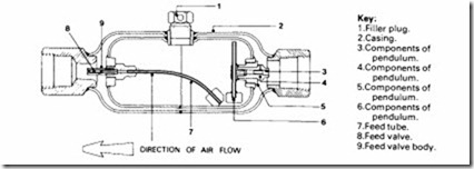
Figure 2 shows an air line lubricator of the first type, used in conjunction with rock drills and other mining equipment. It is placed immediately upstream of the tool. The amount of oil feed is varied by changing the feed valve; other similar types are adjustable by means of a screw. Another example is shown in Figure 3.
Figure 4 is a centralised lubrication system providing fine droplets of oil mist. The cabinet houses a filter, pressure regulators, pressure gauges and warning lamps. This system needs an electric supply, but the Micro-fog lubricator itself can be used as a stand alone unit. The operation of the lubricator is shown in Figure 5. Air introduced into the lubricator pressurises the reservoir and operates a pump supplying oil to liquid level cup; this ensures that oil is drawn from a constant level, eliminating variations in output caused by changing levels in the reservoir itself. Air flow causes oil to be drawn from the cup via
In this design the air stream passes through the space between the outer casing and oil contamer. When the connected tool is in operation there is a pressure drop at the outlet end. Through a smaii port live air is admitted into the container, exerting a pressure on the surface of the oil and forcing the oil past the controiiing valve. A choice of feed valves is made available with each lubricator. Since the valve outlet is situated in the orifice throat, a venturi effect is induced which also serves to draw oil from the container into the air stream. The weighted flexible tube permits practicaiiy ali of the contents of the lubricator to be used irrespective of its location, whilst the weighted pendulum ensures the admission of air to the space above the oil without ailow a ‘leak back’ of oil.
the syphon tube B into the sight feed dome A, where it can be seen to drip onto the venturi plug C. The action of the air at the venturi plug causes a fine mist in the upper part of the reservoir, from where it is delivered to the distribution system. This system produces a particularly fine oil mist as shown in Figure 6.
Another type of centralised lubrication system is exemplified by the oil injector pump in Figure 7, which is able to supply oil in pulses direct to the tool. It is actuated by the air pulse generated when the tool is started. Oil is supplied from the main dispenser, either into the air line or to a lubrication point in the equipment. This equipment can be installed to supply oil to a single tool or to an unlimited number of lubrication points; it is suitable for fixed installations only.
Anti-freeze injectors
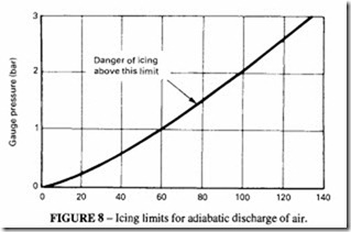
In winter conditions, ice formation can be a serious problem, although it occurs also when the ambient temperature is above freezing. Figure 8 shows that, when the exhaust pressure is high, icing can occur at surprisingly high air temperatures. The incidence of ice formation seems to be related to the presence of moisture in the air as much as to temperature. Measures such as injecting glycol with the oil or rinsing out equipment with alcohol should on no account be used. The best method is the use of dry air but it has to be admitted that this may not be a practical solution, on cost grounds alone, particularly ifthe problem only occurs during winter. Ifthe problem is only in the equipment exhaust, a moisture trap immediately upstream (where the temperature is likely to be closest to ambient) should first be tried.
Another technique, where freezing in the distribution system is the problem, is the installation of an alcohol dispenser immediately downstream ofthe receiver, where the air is warm (but not above 40°C). The alcohol evaporates and condenses in the water traps, preventing the water which is there from freezing. Ifthe amount of alcohol added does not exceed 4-8 drops (0.01 -0.02 em perm of free air), then practically no alcohol will get to the tools where it would wash away the lubricant. A conventional air line lubricator, adjusted to give the recommended injection rate, should be adequate to provide the required degree of protection, or a special proprietary injector can be obtained.
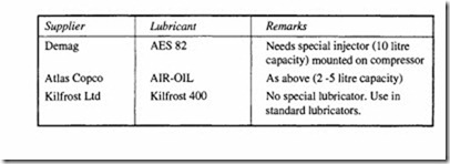
There are also available special anti-frost synthetic lubricants based on glycol with inhibitors, intended to prevent icing in the tools. The following products are available.
These lubricants give protection down to -60°C. They possess some other desirable properties, such as being bio-degradable and emulsifying. They are capable of absorbing up to four times their own weight of water. Particular care should be taken if used in a confined area with poor ventilation as there may be health hazards with prolonged exposure. They are more expensive and may not be satisfactory in all circumstances, so they should only be used after reference to the tool manufacturer.
