Automation and robotics
Compressed air for robotic applications
The versatility and economy of compressed air as a power medium leads to its use in automation and in robots. It is, of course, important that its particular characteristics are thoroughly understood, but once that is done, there are many applications and proprietary products on the market which can be used in robotic applications, more specifically in 3-D Manipulators or “Pick and Place” Modular robots. This subject was briefly covered in the section on pneumatic cylinders, but the subject is of such growing importance that a more extended treatment will be of assistance.
The advantages that compressed air possesses in this application are:
• speed of operation;
• precision (an accuracy ofO.J mm is possible);
• safety in hazardous environments;
• cleanliness for food product processing;
• flexibility of application;
• stroke adjustments are easily made to meet a variety of applications;
• modular kits are available from a number of suppliers, making do-it-yourself robot assemblies a practical possibility;
• integration with electronic control units and with electric power drives.
Available modules
Basically a robotic system comprises some or all of the following modules:
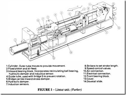
1. Precision linear units for horizontal or vertical movements in a straight line. Some suppliers differentiate between long and short stroke units; the long stroke units are designed to be stiff to carry unsupported loads and include hydraulic damping for end of stroke damping; the short stroke units are attached to the end of the long stroke units for the final precise positioning movement. Although for some applications it is possible to use a conventional pneumatic cylinder or a rodless cylinder with position sensors, in most cases higher precision is required and so special units are used. Figure I shows one form of construction. Another type, shown in Figure 2, incorporates telescopic feed tubes in the unit to supply the air
for the further modules that are attached to it; up to 16 connections are possible. Because of the overhang where these modules are set up for horizontal move ment, the permissible load is severely restricted for long strokes; so reference should be made to the suppliers to ascertain the maximum allowable load for the
envisaged application.
2. Base rotate units on which the linear units are mounted. These are similar to rotary indexing tables using either cylinders or a rotary actuator. Multiple angles in intervals usually of about 15° are available. It is likely that a base unit will have to support an arm which, including its attachments, will have a high rotary inertia; so care should be taken to ensure that the speed is controlled and end-of-stroke cushioning is provided.
3. Wrist rotate units, which are usually mounted on theendofthelinearunits. Angular travel of 180° or in some cases 270° is possible.
4. Grippers for holding components. They may be single acting with spring return or double acting. Different gripping hands to cater for variously shaped components as well as multiple grips for handling several components at a time are also available. Pneumatic chucks may be used for turned components; for glass or metallic sheets, a suction head can also be used. For components made, or partly made, of magnetic materials, a permanent or electro-magnet may be used.
With these four modules it is possible to secure the most complex of transfer motions. Each modular element is provided with induction sensors to detect the end of the stroke
and, in some types, intermediate stroke positions. In addition, it will usually incorporate speed control valves, which are set during development.
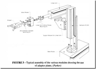
If the user keeps to one supplier, it is possible to use a range of standard mounting kits to link the modules together, but provided one is prepared to makes one’s own connec tions, this is not a necessary restriction. Figure 3 shows how the modules can be connected by the appropriate adaptor plates.
If the velocity of one of the units needs to be governed either to a maximum value or to ensure that the travel is smooth, without end-of-travel bounce, an air/oil tandem cylinder may be incorporated. These are discussed in the chapter on Actuators.
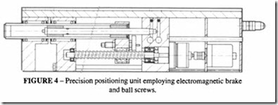
Two further modules, which are modifications of the linear unit, are the precision positioning unit and the gantry unit. The positioning unit allows very precise, infinitely variable stroke length. One type is shown in Figure 4. Power for movement is supplied by the internal cylinder and positioning is achieved by a ball screw linked to an incremental encoder and a magnetic brake. When the encoder signals that the correct position has been
reached, the brake is applied, locking the unit in position. Variable positioning is possible with an accuracy of 0.1 mm. A positioning unit is controlled by a 3-D controller as in Figure 5.
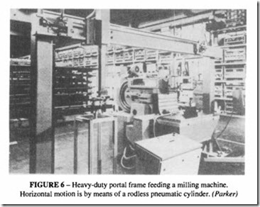
The gantry unit is for applications where the component weight requires a rigid support or where the distances to be traversed are too long for a basic linear unit. Using a rodless cylinder allows a maximum stroke of up to 3 metres, without the load restrictions of an overhung unit. It is more suitable for permanent installations, for it lacks the versatility of the basic linear module. A gantry unit is one example of where a combination of electrical and pneumatic operation is advantageous. As an alternative to a pneumatic cylinder, a d.c. servo-motor can be used to drive the carriage along the gantry to stop at a number of pre determined positions. Figure 6 shows a gantry unit for charging a milling machine. The cylinder is designed to have four stop positions.
Use of multi-motion actuators
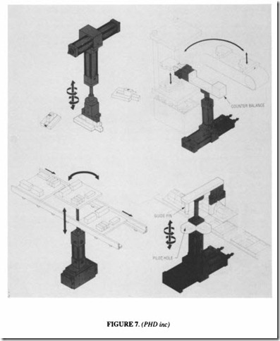
Fairly simple factory automation can be introduced with multi-motion actuators. These provide linear and rotary motion in the same unit and are described in the chapter on Actuators. They can be used, in conjunction with a gripper to position parts for machining or further assemblies. Some possibilities are shown in Figure 7.
Control systems
The versatility of robotic operation can only be realised with a well-designed programma ble controller (PLC), of which there are several on the market. A 3-D controller can be linked directly to a PLC. Manufacturers of pneumatic components can also offer PLCs which interface with their own equipment, and which can be programmed either with the help of a personal computer or a hand-held programmer, using a standardised form of programming.
There are also pneumatic logic components which allow the control to be done purely pneumatically. These are discussed in the chapter on Circuit Analysis.
Fieldbus systems
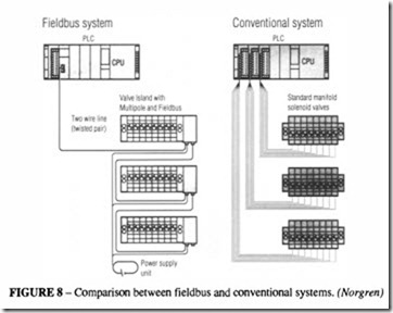
There has been much interest in recent years in the development of controls based on a two wire cable (a fieldbus), rather than the conventional cabling normally associated with solenoid valves and read-out devices. The great advantage of a field bus is the reduced wiring requirements, with space saving and low maintenance. The digital signal and processing allows factory control with a much simpler system than hitherto. Figure 8 compares a fieldbus with a conventional system. Baud rates of up to 12 Mbits/s are possible with a standard fieldbus. RS 485 is the standard communication technology.
To take advantage of this form of control, pneumatic solenoid valves with the appropriate digital signalling have to be available, as does the appropriate interface with the PLC. Fortunately a number of manufacturers can supply these. One has to choose a suitable protocol, which is common across the various components in use. For a low-cost local system, one might choose Pneubus; one of the most widely promoted international
systems is PROFIBUS; other proprietary systems specific to a single manufacturer, are available.
Valve islands with up to 24 valves on a single island can be pre-wired and ready for use, see Figure 9.
Semi-robotic devices
In addition to these fully automatic systems, there are also available pneumatic manipulators which remain always under manual control but which take the effort out uf the
handling. They incorporate some of the features discussed above, so it is convenient to include them here, but it should be emphasised that they are intended solely to assist the operator and not to replace him. Often, because the movement is always under human control, the operation can be faster than in a pneumatic device.
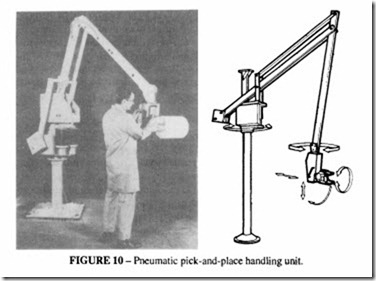
Figure 10 shows a typical pick-and-place handling unit of this kind. The weight of the component (in this example a roll of glass fibre) is reacted through the pantograph mechanism to pneumatic cylinders in the base of the unit. The grippers are pneumatically actuated, but apart from this the placing of the component is performed by the operator. A number of special optional features can be built into this system; the payload can be either completely balanced or, in cases where varying weights have to be moved, by a lever under the operator’s control. Safety features are built in, so that if the air pressure is suddenly lost or if the payload becomes detached, the system remains fail-safe.
