AIR MOTORS
General characteristics
Air motors should not be looked upon as a substitute for hydraulic or electric motors. They have their own characteristics which make them ideal in certain applications.
They offer a compact and lightweight source of rotary power, reversible and easily adjustable in speed and torque. They possess characteristics similar to those of d.c. series wound electric motors.
Air motors can be stalled indefinitely and start immediately with maximum torque.
They can be designed to produce equal power in either direction of rotation, merely by reversing the supply and exhaust ports, although maximum efficiency is usually obtain able only when the rotation is uni-directional. They can operate at any speed throughout their design range, and are easily geared to produce maximum power at any required shaft speed. They can be run from any available compressed gas, eg from natural or a process gas. They can be run at any attitude.
When comparing pneumatic motors with the alternative using hydraulic or electric power, the following should be borne in mind:
• There is no heat build-up when continuously stalled. When the load is reduced to allow the motor to turn, it will resume normal operation. They can tolerate being driven counter to the applied pressure. The air flow through the motor acts as a self cooler.
• Maintenance is low compared with hydraulic motors.
• There is no sparking, so they are safe in explosive atmospheres. In wet conditions, there is no shock hazard.
• When compared with electric motors they have a higher power/weight ratio (for the same output, the weight is about one-third).
• The moment of inertia is lower than electric and hydraulic motors, so they reach maximum speed quickly and brake instantly.
• They can be installed and operated in any position from horizontal to vertical.
Performance characteristics
All pneumatic motors of any design possess similar theoretical performance characteris tics, illustrated in Figure 1. The torque is a maximum at zero speed, although in practice
(as shown in Figure 1), there tends to be a fall-off at stall conditions, caused by break-out friction and by the variable starting position of the vanes or the pistons. Starting torque, (the torque produced by a stationary motor) is about 75% of the stall torque (the maximum torque which will stall the motor), although for some designs it can be as little as 50%. Manufacturers quote minimum and maximum starting torque values, which may differ considerably, according to the starting position of the shaft. If starting torque is an installation parameter, the correct value must be taken. For winches and hoists which may have to start under load, the minimum starting torque is the design criterion; for motors which start off-load, such as for fan drives, the maximum running torque will dominate the choice.
When the motor is stalled, the power is zero. As the speed increases, the torque falls linearly until it reaches zero at its free speed. This linear torque/speed relationship results in the power being a maximum at a speed equal to one-half the free speed. Each curve of this kind is valid for one applied pressure. Where motors are suitable for operation at a variety of inlet pressures, then a family of such curves can be drawn.
One of the important features of air motor behaviour is that maximum power occurs at halffree speed.
It is necessary to know the relationship between power and speed before a rational selection can be made of a suitable motor. Most manufacturers of air motors offer a matching range of gear boxes, which allow one motor to be used for a range of speeds. Figure 2 shows how the same motor can be modified to give different characteristics by merely changing the gearing.
These curves are, of course, theoretical; an examination of published curves of commercial motors would show deviations from theory. In particular, most motors are speed limited by some kind of governor, which progressively throttles the air supply as the speed increases. One type of governor is the centrifugal type illustrated in Figure 3. A governor distorts the shape of the high speed end of the power curve, see Figure 4, so as
to limit the maximum speed; it should not affect the peak power. One basic motor can have its characteristics changed by altering the governor weights or spring stiffness.
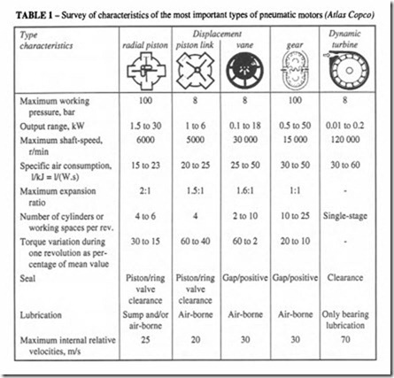
Table 1 shows the most popular types of motors that are available, with their characteristics.
Vane motors
These motors are similar in concept to vane compressors. Torque is developed by pressure difference on the vanes. There may be between 3 and 10 vanes per motor, but usually 4 or 6. Vanes are usually radial (the centre line of the vane passes through the axis of the motor), but some manufacturers prefer to angle the vanes slightly off the vertical. Vane motors are recommended for high speed operation up to 30 000 r/min. They tend not to be very effective at low speed, because they rely on centrifugal force to seal the periphery of the vanes and without this seal, the pressure cannot be sustained. The air pressure is usually limited to 6 bar in vane motors.
The more usual vane motor is a single chamber, but it is also possible to make a dual chamber motor. The two are shown in Figure 5. The advantages of a dual chamber are a higher torque at lower operating speeds.
The detailed design of an air motor differs according to whether or not it is intended to be reversible. Reversible operation is achieved by making the inlet port into the exhaust and vice versa; such a design is bound to be a compromise, so rather better efficiencies are available in single direction motors.
The vanes are the vulnerable components of a motor. At very high speed the centrifugal force is so high that frictional forces can cause rapid wear; and at low speed the centrifugal force is too low to ensure sealing contact at all times. If a motor is continuously operated at low speed or under conditions of frequent reversals of direction, the vanes tend to hammer the stator and suffer impact failure. A variety of different materials have been tried for vane manufacture but it has been found that resin-impregnated, fibre-reinforced materials are generally best; carbon reinforced materials are used for heavy duties. The conditions in a motor are quite different from those in a vane compressor, where the speed range is limited, so the same vane materials will not necessarily do. Good air-mist lubrication is essential to reduce friction and wear. The air should be filtered to 64 micron or better. Refer to the manufacturers for recommendations for suitable lubricants. There may be different lubricants specified for the gear-box, the bearings and the oil mist.
Small vane motors are use for hand tools such as drills, grinders and screwdrivers. They
often incorporate a step down gear box in the main casing as in Figure 6. Larger sizes are used for winches, pump drivers, drive motors on pneumatic drill rigs and general industrial applications. Figure 7 shows a large foot-mounted industrial vane motor.
Piston motors
Piston motors operate at lower speeds than vane motors, the limiting factor being the inertia of the reciprocating parts. Free running speed is usually 3000 r/min or less, with the maximum power being developed at I 000 to 2000 r/min.
The majority of piston motors are multi-cylinder units, which may be in-line, vee, H,
flat-four, radial or other variants. In the main, however, the vee is the most popular configuration, with the radial configuration equally popular for three or more cylinders. A radial configuration offers the possibility of weight reduction and is frequently adopted for larger motors. Either an odd or even number of cylinders can used; three-, four-, five and six-cylinders are commonly found.
The vee-four motor normally has two cylinder banks at 90° to each other. Drop forged two-throw crankshafts are normally used with two connecting rods on each crank pin. Distribution valves may be oscillatory or rotary. Valve timing can be arranged to give equal power in each direction, or may be biased to provide asymmetrical timing and increased speed and power in one direction of rotation.
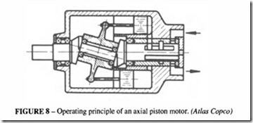
The typical radial motor has all connecting rods mounted on a common crank as in Figure 8. Power and exhaust strokes are controlled by suitable distribution valves and a two-stage exhaust is often adopted. In this case the inlet valve opens just after top dead centre and remains open for 160°; the inlet valve then closes and a large primary exhaust valve opens quickly to release the air to atmosphere. After a further 40° of rotation, this valve closes and a smaller exhaust valve opens to continue the evacuation of the air.
Reversal of direction of rotation is obtained by interchanging the inlet and secondary exhaust connections, which can be done by means of a control valve some distance away from the motor.
Axial piston motors can have 4, 5 or 6 pistons, but are limited to smaller sizes, less than kW. They have the advantage of low inertia, high starting torque and so they reach operating speeds almost instantly. See Figure 9.
Piston motors develop high starting torque, which falls with increasing speed. Both the torque and power are directly dependent on supply air pressure. The torque characteristics can be modified to some extent by detailed design such as the valve timing and valve sizes. They are positive displacement machines, so the air consumption is directly related to speed, within the limitation of the air passages to supply that air. Power output is of the order of 5 to 10 kW!litre of cylinder volume.
Running speeds are generally low to moderate, although small machines may be designed to run at high speeds.
Motors may have output gears to increase the torque and lower the speed.
The overall characteristics of piston motors make them suitable for a wide range of applications. With modification somestandarddesignscan often work satisfactorily down to 0.35 bar. Continuous lubrication is essential and the method oflubrication is dependent upon the design and the need to separate the various lubricants that may be used. A lubricant containing an emulsifying agent may be desirable in a cylinder to prevent water washing, but would not be suitable for splash lubrication in a crank case.
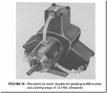
Another variation of piston motors employs a free piston acting on an elliptic cam ring illustrated in Figure 10. The air supply to the cylinder comes from a rotary valve on the main output shaft. Because the design has no need of a connecting rod, the air supply need not be lubricated, which makes it useful for process industries where the presence of oil could not be tolerated. This type of motor is available with either a metal or plastic (acetal) body. It is particularly suitable for low speed applications (up to 800 r/min), and can be driven through a reduction gear box for slow speed process control applications.
Turbine motors
These are very high speed motors capable of generating a small torque only; in the stalled condition the torque is practically negligible. The range of speeds is limited in the range of 50 000 to 80 000 r/min, with the torque a maximum in the mid-range. Applications are limited to those where high speeds with light loads are suitable- high speed pencil grinders and dental drills. Like other air motors a turbine motor can be stalled without damage. Some turbine motors can be fitted with mechanical governors to limit the maximum speed. Turbine motors operate with clearances throughout, with no sliding or rubbing other than the bearings. Bearing friction is thus the limiting factor governing free speed. Turbines can operate well on dry air- no lubrication other than in the bearings which can be self-lubricating or have their own lubrication system; this can bean advantage in certain applications.
Impulse turbine motors
Originally developed in small powers up to 2.25 kW, very much larger turbine motors are now available up to 70 kW. These are normally single-stage impulse turbines coupled to a planetary gear reduction set. They are competitive with vane and piston motors, being smaller and lighter for the same size.
Gear type motors
These motors are based on the meshing together of gears. The simplest and most common type of gear motor is based on a spur gear pair (Figure 11), although other types are available. Helical gear motors have better sealing characteristics and for that reason are claimed to be more efficient in the use of air, but they are more expensive. A helical gear motor having an axial rather than a radial flow path, designed to the same principles as a screw compressor, is likely to be the most efficient of all, but except for special applications its cost will be prohibitive.
Roots motors (similar to the Roots compressor, described in the Compressor chapter) can be included in this category, but they have an inherently high leakage rate and are not normally competitive as motors.
As can be seen from Figure II, there is little or no expansion of the air between admission and exhaust, compared with the vane or piston type, and this limits the power that can be extracted from the air. In spite of this the spur gear motor is in practice as efficient as a vane or piston motor and, provided that adequate lubrication is supplied with the air, is very robust and has a long life. One advantage of a gear motor is that there is very little variation between minimum and maximum starting torque, which makes it suitable for such applications as starter motors. It is more compact than the radial piston motor and has better low-speed performance than the vane motor.
Motor control systems
The simplest control system is a manual on/off valve. For reversible motors a two way spool valve is required, which may be operated either by a simple hand control or remotely. Differential power in forward and reverse directions (as may be required in hoists) can be achieved in three ways:
• through pressure control valves in the supply lines,
• by a biased power spool valve,
• by a restriction in the lines.
A common requirement on air motors is an automatic brake to prevent creep when the air is turned off; it is essential for hoists and winches which have to hold the load safely. Most manufacturers supply the brake as a module, mounted on the output face of the motor. It consists of two spring-applied shoes pressed against a central hub. When air is applied to either of the input ports, a shuttle valve sends air to the brake which overcomes the springs, allowing the motor to turn. See Figure I2.
Gear boxes for air motors
Manufacturers supply gear boxes for industrial motors, either flange or base mounted. One company, for example, offers gear boxes with ratios from 2.3 : Ito 85 : I.Gearing may
be spur, helical, bevel or worm. Figure 13 shows how a basic motor may be supplied with a variety of different controls, brakes and gear boxes. An efficiency of about 85% can be assumed for the gears.
Summary of characteristics of air motors
It will be apparent that air motors are available to meet a variety of applications, and so performance characteristics should be obtained from the manufacturers. From published data on power output, the values of Table 2 have been selected.
The rotational speed at which the maximum power is reached depends on the motor design.
Motors chosen are a small selection of those available. Pressure 6 bar, except where quoted.


