Air films
The use of an air cushion to reduce friction is well known in various applications- air bearings, the floating of one machine surface over another and moving heavy loads. A similar analytical approach can be adopted for all these applications.
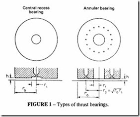
A thrust bearing can adopt one of the fonns shown in Figure 1-a central recess or an annular bearing.
The load that such a bearing can support is given by
F is the load carried, CL is the load coefficient, A is the total pad area(= 1tr 2) and P the supply pressure (gauge). The value of CL can be estimated from Figure 2. It can be seen that for bearings with small pockets, a value of C = 0.25 is a reasonable approximation and this value is often taken as an initial estimate. The basic principle to be used for calculating the feed orifice diameter is that it should be smaller than the circumferential leakage area, i.e. the orifice area must be greater than 21troh. This should ensure that the suspension system is stable, although if maximum stability is required, unpocketed orifices are preferred.
The value of h is very small when smooth machined surfaces are employed (typically 0.025 mm). When the application is for moving loads over rough surfaces, care should be taken that h is greater than the roughness.
Bearings for use on precision surfaces
An important application of air bearings is their use for moving heavy components over surface plates and machine-tool surfaces. Precision surfaces are expensive to produce and subject to wear in use, resulting in progressive deterioration. Air bearings can be used to overcome this problem and also to allow for ease of manipulation.
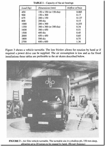
In these bearings, the air thickness is about 0.025 mm with a surface pressure of Ito 2 bar. The air flow requirements are modest, but the air quality should be good; dry filtered air is necessary so that there is no chance either of corrosion or dirt affecting the surface. The air supply for commercially available bearings is taken from shop air. Table Igives typical data.
It is not necessary that the surface over which the bearing moves shall be continuous.
If the surface has slots or holes, the bearing will work with a reduced capacity approximately proportional to the area that remains unvented.
The same principle of using air bearings is adopted in more permanent installations on rotary tables used for paint spraying, welding fixtures and for work transfer tables.
Air skates
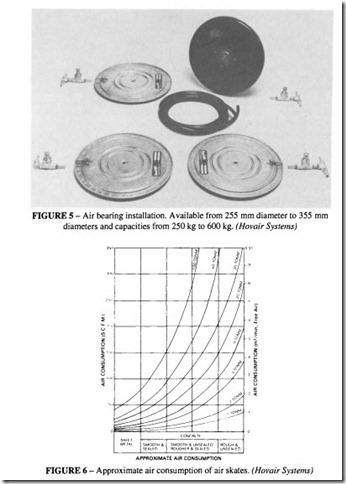
These are suitable for moving machine tools and other heavy loads over a concrete or other level floor. The method of operation is shown in Figure 4, and a set of four bearings supplied ready for installation in Figure 5. Three or more of these skates are required for stability under load. The air pressure (usually shop air at 5 to 6 bar) inflates the urethane diaphragm creating a pressure zone which lifts the load until controlled air leakage forms a thin film between diaphragm and floor. Once floating on its air film, the load is virtually frictionless and may be moved in any direction with a minimum of effort. The ground pressure, which varies with the quality of the operating surfaces, is from I to 4 bar. The air consumption also depends on the quality of the surface as in Figure 6. It is really only practical to use these skates over a reasonably smooth surface. As can be seen from the
figure, the air consumption rises rapidly with increasing roughness; a temporary smooth surface such as a steel sheet may have to be laid where the surface is very rough.
To give some idea of the size and lift of a typical skate, Table 2 gives typical information.
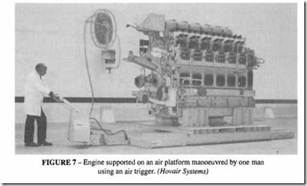
Figure 7 shows how a 40 tonne engine, supported on an air film platform can be moved by an air operated tugger.
Journal and thrust bearings
These are of two types: self-acting and externally pressurised.
Self-acting bearings are similar in principle to liquid hydrodynamic bearings. They are used in the form of smooth surface cylindrical journals and flat thrust bearings. The main drawback of air bearings in this form is that they lack the boundary lubrication property of liquid lubricants so they have high friction at start and stop, limiting their use to about bar over the projected bearing area. This is a subject where expert knowledge is required for design.
Externally pressurised bearings are used in high speed (of the orderof25 000 rev/min),
low friction applications for such purposes as diamond machining and dicing (precision machining of semiconductor materials) as illustrated in Figure 8. Factors influencing the design are: pocketed or non-pocketed feed holes, bearing stiffness to achieve the desired resonant frequency, available pressure. For very high speed applications, water cooling is incorporated in the bearings. Charts are available for detailed design purposes, see for example Tribology Handbook published by Butterworth.


