Application notes
Speed control
The operational speed of an actuator is determined by the fluid flow rate and the actuator area (for a cylinder) or the displacement (for a motor). The physical dimensions are generally fixed for an actuator, so speed is controlled by adjusting the fluid flow to (or restricting flow from) the actuator. Rotary actuator speed can also be con trolled by altering swash plate angle.
The compressibility of air, normally advantageous where smooth operation is concerned, makes flow control more difficult for pneumatic than hydraulic systems. Although techniques described below can be applied in pneumatics, precise slow-speed control of a pneumatic actuator is achieved with external devices described later.
There are essentially four ways in which fluid flow can be con trolled. The first is shown in Figure 5.30, where a pump delivers a fluid volume V per minute. Because the pump is a fixed displacement device this volume of fluid must go either back to the tank or to the actuator. When the control valve moves from its centre position, the actuator moves with a velocity:
where A is the piston area. If pump delivery volume V can be adjusted (by altering swash plate angle, say,) and the pump feeds no other device, no further speed control is needed.
Most systems, however, are not that simple. In the second speed control method of Figure 5.31, a pump controls many devices and is loaded by a solenoid-operated valve (see Chapter 2). Unused fluid goes back to the tank via relief valve V3. The pump output is higher than needed by any individual actuator, so a flow restrictor is used to set the flow to each actuator. This is known as a ‘meter in’ circuit, and is used where a force is needed to move a load. Check valve V 1 gives a full-speed retraction, and check valve V2 provides a small back pressure to avoid the load running away. The full pump delivery is produced when the pressure reaches the setting of relief valve V3, so there is a waste of energy and un necessary production of heat in the fluid.
If the load can run away from the actuator, the third speed control method; the ‘meter out’ circuit of Figure 5.32 must be used. As
drawn, this again gives a controlled extension speed, and full retraction speed (allowed by check valve V 1). As before, the pump delivers fluid at a pressure set by the relief valve, leading to heat generation.
Finally, in the fourth speed control method of Figure 5.33, a bleed-off valve V 1 is incorporated. This returns a volume v back to
the tank, leaving a volume V-v to go to the actuator (where Vis the pump delivery volume). Pump pressure is now determined by the required actuator pressure, which is lower than the pressure set on the relief valve. The energy used by the pump is lower, and less heat is generated. The circuit can, however, only be used with a load which opposes motion. Check valve V2 again gives a small back pressure.
Any unused fluid from the pump is returned to the tank at high pressure leading to wasted energy; even with the more efficient ‘bleed’ -off circuit. One moral, therefore, is to have a pump delivery volume no larger than necessary.
Figures 5.31 to 5.33 imply flow, and hence speed, is set by a simple restriction in piping to the actuator. While a simple restriction reduces flow and allows speed to be reduced, in practice a true flow control valve is needed which delivers a fixed flow regardless of line pressure or fluid temperature.
An ideal flow controller operates by maintaining a constant pressure drop across an orifice restriction in the line, the rate being adjusted by altering orifice size. The construction of such a device is shown in Figure 5.34. The orifice is formed by a notch in a shaft which can be rotated to set the flow. The pressure drop across the orifice is the difference in pressure between points X and Y, and is applied to the moveable land. The pressure at X, in conjunction with the spring pressure, causes a downward force, while pressure at Y causes an upward force. If the land moves up the flow reduces,
if the land moves down the flow increases. The piston thus moves up and down until the pressure differential between X and Y matches the spring compressive force. The device thus maintains a constant pressure drop across the orifice, which implies constant flow through the valve, and is known as a pressure-compensated flow control valve.
Flow control valves can also be adversely affected by tempera ture changes which alter the viscosity of the oil. For this reason more complex flow control valves often have temperature compensation. Symbols for various types of flow control valves are given in Figure 5.35.
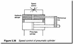
Discussions in this section have, so far, been concerned with hydraulic systems as compressibility of air makes speed control of pneumatic actuators somewhat crude. If a pneumatic actuator is required to act at a slow controlled speed an external hydraulic damper can be used, as shown in Figure 5.36. Oil is forced from one side of the hydraulic piston to the other via an adjustable flow control valve. Speeds as low as a few millimetres a minute can be accurately controlled in this manner, although the technique is physically rather cumbersome.
Actuator synchronisation
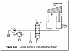
Figure 5.37 illustrates a common problem in which an unbalanced load is to be lifted by two cylinders The right-hand cylinder is
subject to a large force F, the left-hand cylinder to a smaller force f. The right-hand piston requires a pressure ofF/A to lift, while the left-hand piston needs f/A. When lift is called for on valve V1, the pressure rises to the lower pressure f/A, and only the left-hand piston moves. The unbalanced load results in faulty operation. A similar result can occur where two, or more, cylinders operate against ill-defined frictional forces.
One simple solution is the inclusion of flow regulating valves. A flow control valve can set, and hold, fluid flow to within about ±5% of nominal value, resulting in a possible positional error of 10% of the stroke. This may, or may not, be acceptable, and in the example of Figure 5.37 the cylinders would, in any case, align themselves at each end of the stroke. (When the most lightly laden and hence fastest travelling piston reaches the end of its stroke, the system pressure will rise.) This solution is not acceptable if good position al accuracy is required or rotary actuators without end stops are being driven.
The flow divider valve of Figure 5.38 works on a similar principle, dividing the inlet flow equally (to a few percent) between two outlet ports. The spool moves to maintain equal pressure drops across orifices X and Y, and hence equal flow through them.
The displacement of a hydraulic or pneumatic motor can be accurately specified, and this forms the basis of an alternative flow divider circuit of Figure 5.39. Here fluid for two cylinders passes through two mechanically coupled motors. The mechanical coupling ensures the two motors rotate at the same speed, and hence equal flow is passed into each cylinder.
The two cylinders in Figure 5.40 are effectively in series with fluid from the annulus side of cylinder 1 going to the full bore side of cylinder 2. The cylinders are chosen, however, so that full bore area of cylinder 2 equals the annulus area of cylinder 1. Upon cylinder extension, fluid exits from cylinder 1 and causes cylinder 2 to extend. The two cylinders move at equal speed because of the equal areas.
There is, though, an unfortunate side effect. Pressure P2 in cylin der 2 is F/a. Fluid on the full bore side of cylinder 1 has to lift the piston against force f plus the force from P2 acting on the annulus side of the piston. Pressure P1 is (F+f)/A; higher than would be
required by two independent cylinders acting in parallel. The rotational speed of motors with equal displacement can similarly be synchronised by connecting them in series. Inlet pressure of the first motor is again, however, higher than needed to drive the two motors separately or in parallel.
None of these methods gives absolute synchronisation, and if actuators do not self-align at the ends of travel, some method of driving actuators individually should be included to allow intermit tent manual alignment. The best solution, however, is usually to include some form of mechanical tie to ensure actuators experience equal loads and cannot get out of alignment.


