Air flow rate control
If the air to be used for conveying, is taken from a plant air supply, or some central source, it will probably be necessary to put a flow restriction into the pipeline. This will be needed in order to limit the quantity of air drawn to that of the volumetric flow rate actually required. If this is not done an uncontrolled expansion will occur and very much more air than necessary will be used. It will only be limited by the volumetric cap- ability of the supply, or by the increased frictional resistance of the flow in the pipe- line. The increased air flow rate will almost certainly result in a decrease in the material flow rate through the pipeline. It will also add significantly to problems of erosive wear and particle degradation.
Flow restrictors may also be required in situations where the air supply needs to be divided, as in blow tank systems. For the control of many types of blow tank it is necessary to proportion the air supply between the blow tank and the conveying line. If the total air supply is set, a flow restrictor can be placed in one or both of the divided lines. This, however, can only be done if the blow tank is dedicated to a single material conveyed over a fixed distance. For systems handling more than one material, or conveying to a number of hoppers over varying distances, a variable flow control would be needed. In these cases special control valves would be required rather than fixed restrictors.
Nozzles and orifice plates are most commonly used for restricting the air flow in a pipeline. Under certain flow conditions they can also be used to meter and control the air flow.
Nozzles
For the single phase flow of fluids through nozzles the theory is well established, and for a gas such as air it is based on the use of many of the equations already presented. Nozzles are either of the convergent–divergent type, as shown in Figure 10.13a, or are convergent only, as shown in Figure 10.13b. Both types restrict the flow by means of a short throat section at a reduced diameter.
Critical pressure
A peculiarity of the expansion of the flow of a fluid through a nozzle is that as the downstream pressure, p2, reduces, for a given upstream pressure, p1, the pressure at the throat, pt, will not reduce constantly with downstream pressure. The pressure at the throat will reduce to a fixed proportion of the inlet pressure, and any further reduction of the downstream pressure will not result in a lowering of the pressure at the throat.
Under these conditions the nozzle is said to be ‘choked’. When critical flow conditions exist, the velocity at the throat will be equal to the local sonic velocity. The air mass flow rate through a nozzle is a maximum under choked flow conditions and no reduction of the downstream pressure, below the critical throat pressure, will result in any change of the air mass flow rate.
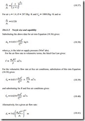
It can be shown (e.g. [4]) that the ratio between the throat pressure and the supply or inlet pressure is given by:
Nozzle types
The above analysis applies to either convergent–divergent or to convergent nozzles. For convergent nozzles, however, the range of operation is limited to downstream pressures less than 52.8 per cent of the upstream pressure, that is, below the critical pressure ratio. With convergent–divergent nozzles this range can be extended significantly, and for a well-made nozzle it can be as high as 90 per cent of the upstream pressure, with little deviation from the predicted flow rate.
Orifice plates
These are frequently used for measuring the flow rate of gases through pipelines but can also be used to choke the flow and so limit the throughput. The orifice consists of a thin plate which is usually fitted into a flanged joint in the pipeline. It has a sharp edged opening which is concentric with the pipe.
The above analysis also applies to orifice plates. There is, however, a coefficient of discharge associated with orifice plates and this has the effect of reducing the flow rate to about 61 per cent of the theoretical value. This means that the constants in Equations (10.35)–(10.40) would have to be multiplied by Ö0.61 a factor of 0.61 and the constant in Equation (10.41) would have to be divided by to take account of this coefficient of discharge. As with the convergent nozzle, the range of operation is limited to down- stream pressures below the critical pressure ratio.
Flow rate control
It will be seen from Figure 10.14 that, for a given nozzle, the air flow rate can be varied over a wide range simply by varying the air supply pressure. In a pipeline from a service supply, a diaphragm valve could be positioned upstream of the flow restrictor, and this could be used to vary the inlet pressure and hence the air flow rate. Provided that critical flow conditions exist, only the inlet air pressure and temperature, and the throat diameter, are needed to evaluate the air flow rate, as will be seen from Equation (10.38).
It will be noticed that, apart from including a representative coefficient of contraction for orifices, no other coefficients have been included in the analysis to allow for friction and other irreversibility in the flow. For most pneumatic conveying applications it will not be necessary, as these losses are generally quite small. If these devices are to be used for flow measurement purposes, however, with a need for a high degree of accuracy, either the loss factors will have to be taken into account or the device will have to be calibrated before being used.


