Stepped pipeline systems
Figures 9.6–9.8 show quite clearly the nature of the problem of single bore pipeline conveying, with respect to air expansion and hence conveying air velocities, particularly where high pressures or vacuums are employed. For both long distance, and dense phase conveying, it is generally necessary to have a fairly high air pressure at the start of the conveying line. As the pressure of the conveying air decreases along the length of the line, its density decreases, with a corresponding increase in velocity, as illustrated above. A simple means of limiting the very high velocities that can occur towards the end of a pipeline is to step the pipeline to a larger bore once or twice along its length. By this means it will be possible to keep the conveying air velocity within reasonable limits.
The ultimate solution, of course, is to use a tapered pipeline, for in this the convey- ing air velocity could remain constant along the entire length of the pipeline. This, however, is neither practical nor possible, but it does provide the basis for a model of what is required. A stepped pipeline, therefore, should be designed to achieve a velocity profile that is as close as practically possible to a constant value.
Step location
The critical parameter in the design of any pipeline is the minimum value of conveying air velocity, for the given material and conveying conditions. In the design of a stepped pipeline system it is essential to ensure that the conveying air velocity does not fall below the minimum value anywhere along the length of the pipeline. In this respect it is the location of the step to each larger bore section of the pipeline that is crucial. With the air expanding into a larger bore pipe the velocity will fall, approximately in proportion to the change in pipe section area, at the step. The location of the step, therefore, must be such that the pressure is low enough to ensure that the vel- ocity in the larger bore section at the step does not drop below the given minimum conveying air velocity.
A pipeline having two steps, and hence three sections of pipeline of different bore, is shown diagrammatically below in Figure 9.10. Reference numbers are assigned to the start and end of each section, and provided that there is no leakage of air into or out of the pipeline between the material feed point at ① and the discharge point at ➅, the air mass flow rate will remain constant and the continuity equation can be used to equate conditions at any point along the length of the stepped pipeline.
By combining Equations (9.5) and (9.6) and substituting from Equation (9.2) gives:
This will give the conveying air velocity at the start of the second section of the stepped pipeline. By equating to the free air conditions in this way, the velocity at any section of the pipeline can be evaluated. If it is the pressure at a step in the pipeline that is required Equation (9.12) can be rearranged to give:
It should be noted that since the end of one section of pipeline terminates at the point where the next section of pipeline starts, the pressure difference between these two points can be disregarded, and so in the above case p2 p3 and p4 p5. It would
generally be recommended that a tapered expansion section should be used to join any two sections of pipeline at a step.
Dilute phase conveying
Figure 9.11 illustrates the case of a dilute phase conveying system, typically for a long distance conveying application.
The minimum conveying air velocity that must be maintained for the material is about 15 m/s, and 60 m3/min of free air is available to convey the material. The conveying line inlet air pressure is 4 bar gauge. From Figure 9.11 it will be seen that a 125 mm bore pipeline will be required for these conditions, and the resulting conveying line inlet air velocity will be 16.5 m/s.
If a single bore pipeline was to be used for the entire length of the line the conveying line exit air velocity would be 81.5 m/s. The inlet air pressure is 4 bar gauge, which is approximately 5 bar absolute, and so if the discharge is to atmospheric pressure, a near fivefold increase in air velocity can be expected. If the material being conveyed is only slightly abrasive, severe wear will occur at any bend towards the end of the pipeline, because of the excessive velocity, and significant degradation of the conveyed material will also occur, even if the material is not particularly friable.
If the velocity was allowed to rise to 30 m/s in this 125 mm bore pipe a change to a 150 mm bore pipe would only reduce the velocity to 21 m/s. The velocity in a 200 mm bore pipe would be about 12 m/s, however, and this is unlikely to be accept- able. A 175 mm bore pipe would probably be satisfactory, but care must be taken that standard pipe sizes are selected. Even in a 175 mm bore pipeline the velocity at exit would be over 40 m/s and so it is clear that two steps and three different pipe sizes would be required.
The velocity profile for a possible combination of 125, 150 and 200 mm bore pipes is shown superimposed in Figure 9.11, but even with this the exit velocity is about 32 m/s. A plot similar to that shown in Figure 9.11, however, will give a clear indication of what is possible. The velocities at the six reference points along the pipeline are also presented on Figure 9.11 and these can be evaluated by using Equations (9.12) and (9.13).
Dense phase conveying
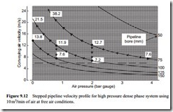
Figure 9.12 illustrates the case of a dense phase conveying system. The minimum conveying air velocity that must be maintained for the material is about 6 m/s, and 10 m3/min of free air is available to convey the material. The conveying line inlet air pressure is 4 bar gauge. From Figure 9.12 it will be seen that a 100 mm bore pipe- line will be required for these conditions, and the resulting conveying line inlet air velocity will be 7.6 m/s. If a single bore pipeline is used the conveying line exit air velocity will be 38.2 m/s.
Although this might be accepted in a dilute phase conveying system it is quite unnecessary in a dense phase system. Apart from reducing problems of erosive wear and particle degradation, by reducing conveying air velocities, a stepped pipeline is also likely to achieve an improved conveying performance, compared with a single bore pipeline, for the same air flow conditions. The velocity profile for a combination of 75, 100 and 125 mm bore pipes is shown superimposed in Figure 9.12. This has resulted in the conveying air velocity being confined to a relatively narrow band, with the maximum value being limited to only 13.8 m/s.
A maximum value of velocity (13.8 m/s) is below the minimum value of velocity that would be used for a dilute phase conveying system. In terms of conveying this is not a problem and comes as a direct consequence of the difference in proper- ties between the two classes of material (see Figure 8.3). The only problem may be
with regard to the purging of material from the pipeline and this is considered in Section 9.5.
Vacuum conveying
Although negative pressure systems are limited to a maximum conveying line pressure drop of less than 1 bar, stepping of the pipeline with vacuum conveying systems is just as important as it is with high positive pressure conveying systems. A typical vacuum conveying system is shown in Figure 9.13. It is drawn for a dilute phase system, where a minimum conveying air velocity of 16 m/s must be maintained, using 15 m3/min of free air and exhausting to -0.6 bar gauge (101.3 – 60 41.3 kN/m2 absolute).
If the vacuum was a little higher than 0.6 bar, a step to a third section of pipeline of 200 mm bore would be required. Even with a conveying line exit air pressure of -0.4 bar gauge a step could be usefully incorporated, as will be seen in Figure 9.13. As the slope of the constant pipe bore curves increase at an increasing rate with decrease in pressure, as discussed earlier in relation to Equation (9.11), steps are required more frequently at low air pressures.
Step position
A practical problem that arises from this is the actual positioning of the various steps along the length of the pipeline. As a first approximation, in the absence of any other information, pipeline lengths can be sized in proportion to the conveying line pressure drop for each section, provided that a reasonably uniform value of conveying air velocity is maintained along the length of the pipeline. It can be seen from Figures
9.11 to 9.13 that if there is a risk of the velocity being too low at the start of the next section, and the pipeline blocking, then the transition to the larger pipe size should be moved a little further downstream, where the pressure will be slightly lower.
Pipeline staging
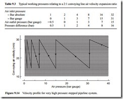
With reference to Figure 9.6 and Equation (9.11) it will be seen that with increase in pressure the slope of the curves decrease. If a stepped pipeline system was to be designed on the basis of a doubling in conveying air velocity, for each section of pipeline, the working pressure for each section of pipeline would increase significantly with increase in pressure, as is shown in Table 9.3.
If it was required to convey a material over a distance of 100 km, it would only be economical if an air supply pressure much higher than 6 bar was to be used. It would also be necessary to divide the system into stages, such that the material was dis- charged from one system, when the pressure had fallen to a given value, and be fed into the next system with high pressure air.
With a conveying line inlet air pressure of 31 bar gauge, for example, the first step would not be necessary until the pressure had fallen to 15 bar gauge, which gives a working pressure difference of 16 bar. If the system discharged to atmospheric pressure, the pressure at entry to the last section of pipeline would be 1 bar gauge and the work- ing pressure difference would only be 1 bar. This effect is illustrated in Figure 9.14, which illustrates the velocity profile for the latter sections of a very high pressure stepped pipeline system in which the material is conveyed in dilute phase.
It would be recommended, therefore, that for a very long distance conveying sys- tem, at the end of each stage along the pipeline, and at the very end of the pipeline, the
material should be discharged at a pressure no lower than about 3 bar gauge. By dis- charging at a high pressure, rather than atmospheric, the last two or three sections of the largest bore pipeline can be dispensed with. The reduction in working pressure drop would be very small in comparison and it would make for a very much simpler pipeline design and layout.


