air treatment
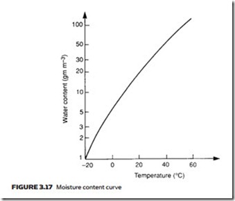
Atmospheric air contains moisture in the form of water vapor. We perceive the amount of moisture in a given volume of air as the humidity and refer to days with a high amount of water vapor as ‘humid’ or ‘sticky’, and days with low amounts of water vapor as ‘good drying days’. The amount of water vapor which can be held in a given volume depends on temperature but does not de- pend on pressure of air in that volume. One cubic meter at 20 °C, for example, can hold 17 grams of water vapor. The amount of water vapor which can be held in a given volume of air rises with temperature, as shown in Figure 3.17.
If a given volume of air contains the maximum quantity of water vapor pos- sible at the air temperature, the air is said to be saturated (and we would per- ceive it as sticky because sweat could not evaporate from the surface of the skin). From Figure 3.17, air containing 50 grams of water vapor per cubic meter at 40 °C is saturated.
Moisture content of unsaturated air is referred to by relative humidity, which is defined as:
Air containing 5 grams of water vapor per cubic meter of air at 20 °C has, from Figure 3.17, a relative humidity of 30%.
Relative humidity is dependent on both temperature and pressure of the air. Suppose air at 30 °C contains 20 grams of water vapor. From Figure 3.17 this corresponds to 67% humidity. If the air is allowed to cool to 20 °C it can only hold 17 grams of water vapor and is now saturated (100% relative humidity).
The excess 3 grams condenses out as liquid water. If the air is cooled further to 10 °C, a further 8 grams condenses out.
The temperature at which air becomes saturated is referred to as the ‘dew point’. Air with 17.3 grams of water vapor per cubic meter has, for example, a dew point of 20 °C.
To see the effect of pressure on relative humidity, we must remember the amount of water vapor which can be held in a given volume is fixed (assuming a constant temperature). Suppose a cubic meter of air at atmospheric pressure (0 bar gauge or 1 bar absolute) at 20 °C contains 6 grams of water vapor (corresponding to 34% relative humidity). If we wish to increase air pressure while maintaining its temperature at 20 °C, we must compress it. When the pressure is 1 bar gauge (or 2 bar absolute) its volume is 0.5 cubic meters, which can hold 8.6 grams of water vapor, giving us 68% relative humidity. At 2 bar gauge (3 bar absolute) the volume is 0.33 cubic meters, which can hold 5.77 grams of water vapor. With 6 grams of water vapor in our air, we have reached saturation and condensation has started to occur.
It follows that relative humidity rises quickly with increasing pressure, and even low atmospheric relative humidity leads to saturated air and condensation at the pressures used in pneumatic systems (8–10 bar). Water droplets resulting from this condensation can cause many problems. Rust will form on unprotected steel surfac- es, and the water may mix with oil (necessary for lubrication) to form a sticky white emulsion, which causes valves to jam and blocks the small piping used in pneumatic instrumentation systems. In extreme cases water traps can form in pipe loops.
When a compressed gas expands suddenly there is a fall of temperature (predicted by expression 1.19). If the compressed air has a high water content, a rapid expansion at exhaust ports can be accompanied by the formation of ice as the water condenses out and freezes.
stages of air treatment
Air in a pneumatic system must be clean and dry to reduce wear and extend maintenance periods. Atmospheric air contains many harmful impurities (smoke, dust, water vapor) and needs treatment before it can be used.
In general, this treatment falls into three distinct stages, shown in Figure 3.18. First, inlet filtering removes particles which can damage the air compressor. Next, there is the need to dry the air to reduce humidity and lower the dew point. This is normally performed between the compressor and the receiver and is termed primary air treatment.
The final treatment is performed local to the duties to be performed, and consists of further steps to remove moisture and dirt and the introduction of a fine oil mist to aid lubrication. Not surprisingly this is generally termed second- ary air treatment.
filters
Inlet filters are used to remove dirt and smoke particles before they can cause damage to the air compressor, and are classified as dry filters with replaceable cartridges (similar to those found in motor car air filters) or wet filters where the incoming air is bubbled through an oil bath then passed through a wire mesh filter. Dirt particles become attached to oil droplets during the bubbling process and are consequently removed by the wire mesh.
Both types of filter require regular servicing: replacement of the cartridge element for the dry type, cleaning for the wet type. If a filter is to be cleaned, it is essential the correct detergent is used. Use of petrol or similar petrochemicals can turn an air compressor into an effective diesel engine – with severe conse- quences.
Filters are classified according to size of particles they will stop. Particle size is measured in SI units of micrometers (the older metric term microns is still common), one micrometer (1 mm) being 10−6 meter or 0.001 millimeter. Dust particles are generally larger than 10 mm, whereas smoke and oil particles are around 1 mm. A filter can have a nominal rating (where it will block 98% of particles of the specified size) or an absolute rating (where it blocks 100% of particles of the specified size).
Microfilters with removable cartridges passing air from the center to the out- side of the cartridge case will remove 99.9% of particles down to 0.01 mm, the limit of normal filtration. Coarse filters, constructed out of wire mesh and called strainers, are often used as inlet filters. These are usually specified in terms of the mesh size, which approximates to particle size in micrometers as follows:
An earlier section described how air humidity and dew point are raised by com- pression. Before air can be used, this excess moisture has to be removed to bring air humidity and dew point to reasonable levels.
In bulk air systems all that may be required is a simple after-cooler similar to the intercoolers described earlier, followed by a separator unit where the con- densed water collects and can be drained off.
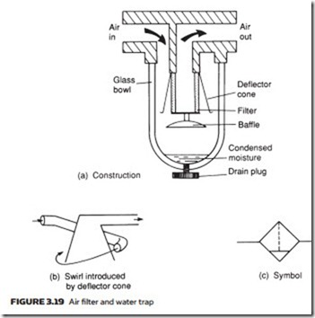
Figure 3.19a shows a typical water trap and separator. Air flow through the unit undergoes a sudden reversal of direction and a deflector cone swirls the air (Figure 3.19b). Both of these cause heavier water particles to be flung out to the walls of the separator and to collect in the trap bottom, from where they can be drained. Water traps are usually represented on circuit diagrams by the symbol in Figure 3.19c.
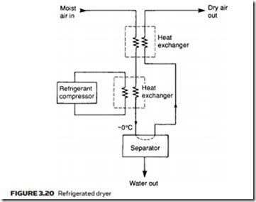
Dew point can be lowered further with a refrigerated dryer, the layout of which is illustrated in Figure 3.20. This chills the air to just above 0 °C, con- densing almost all the water out and collecting the condensate in the separator. Efficiency of the unit is improved with a second heat exchanger in which cold dry air leaving the dryer pre-chills incoming air. Air leaving the dryer has a dew point similar to the temperature in the main heat exchanger.
Refrigerated dryers give air with a dew point sufficiently low for most processes. Where absolutely dry air is needed, chemical dryers must be employed. Moisture can be removed chemically from air by two processes.
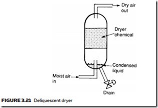
In a deliquescent dryer, the layout of which is shown in Figure 3.21, a chem- ical agent called a desiccant is used. This absorbs water vapor and slowly dis- solves to form a liquid which collects at the bottom of the unit, where it can be
drained. The desiccant material is used up during this process and needs to be replaced at regular intervals. Often, deliquescent dryers are referred to as absorb- tion dryers, a term that should not be confused with the next type of dryer.
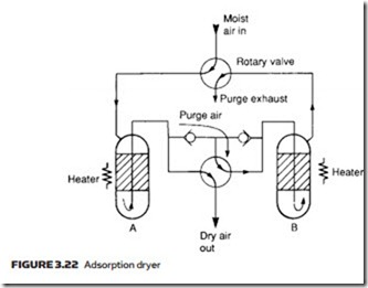
An adsorption dryer collects moisture on the sharp edges of a granular material such as silicon dioxide, or with materials which can exist in hydrated and dehydrated states (the best known is copper sulfate but more efficient com- pounds are generally used). Figure 3.22 shows construction of a typical adsorp- tion dryer. Moisture in the adsorption material can be released by heating, so two columns are used. At any time, one column is drying the air while the other is being regenerated by heating and the passage of a low purge air stream. As shown, column A dries the air and column B is being regenerated. The rotary valves are operated automatically at regular intervals by a time clock. For obvi- ous reasons adsorption dryers are often referred to as regenerative dryers.
lubricators
A carefully controlled amount of oil is often added to air immediately prior to use to lubricate moving parts (process control pneumatics are the exception as they usu- ally require dry unlubricated air). This oil is introduced as a fine mist, but can only be added to thoroughly clean and dry air or a troublesome sticky emulsion forms. It is also difficult to keep the oil-mist-laden air in a predictable state in an air receiver, so oil addition is generally performed as part of the secondary air treatment.
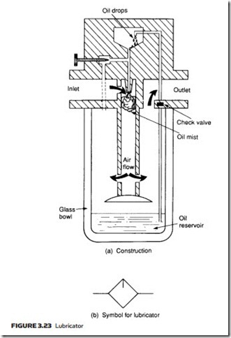
The construction of a typical lubricator is shown with its symbol in Figure 3.23. The operation is similar to the principle of the petrol air mixing in a motor car carburettor. As air enters the lubricator its velocity is increased by a venturi ring, causing a local reduction in pressure in the upper chamber. The pressure differ- ential between lower and upper chambers causes oil to be drawn up a riser tube, emerging as a spray to mix with the air. The needle valve adjusts the pressure differential across the oil jet and hence the oil flow rate.
The air–oil mixture is forced to swirl as it leaves the central cylinder, causing excessively large oil particles to be flung out of the air stream.
air classification
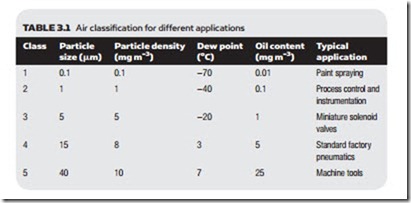
Different applications require different air qualities; very small particles, for ex- ample, can cause unsightly blemishes with paint spraying for motor vehicle bod- ies, and the fine tolerances in process control pneumatics can easily be blocked by high oil content or particles. At the other extreme it is wasteful to have expen- sive high-quality air for workshop machine tools. Standard ISO 8573-1 defines different air qualities, as shown in Table 3.1.
