The vast majority of pneumatic systems use compressed atmospheric air as the operating medium (a small number of systems use nitrogen obtained commercially from liquid gas suppliers). Unlike hydraulic systems, a pneumatic system is ‘open’; the fluid is obtained free, used and then vented back to atmosphere.
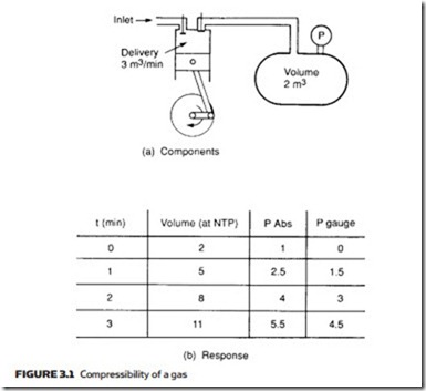
Pneumatic systems use a compressible gas, hydraulic systems an incompressible liquid, and this leads to some significant differences. The pressure of a liquid may be raised to a high level almost instantaneously, whereas pressure rise in a gas can be distinctly leisurely. In Figure 3.1a, a reservoir of volume two cubic meters is connected to a compressor which delivers three cubic meters of air (measured at atmospheric pressure) per minute. Using Boyle’s law (expres- sion 1.17) the pressure rise shown in Figure 3.1b can be found.
Pressure in a hydraulic system can be quickly and easily controlled by devices such as unloading and pressure-regulating valves. Fluid is thus stored at atmospheric pressure and compressed to the required pressure as needed. The slow response of an air compressor, however, precludes such an approach in a pneumatic system and necessitates storage of compressed air at the required pressure in a receiver vessel. The volume of this vessel is chosen so there are minimal deviations in pressure arising from flow changes in loads and the compressor is then employed to replace the air used, averaged over an extended period of time (e.g. a few minutes).
Deviations in air pressure are smaller, and compressor control is easier if a large receiver feeds many loads. A large number of loads statistically results in a more even flow of air from the receiver, also helping to maintain a steady pressure. On many sites, therefore, compressed air is produced as a central service which is distributed around the site in a similar manner to electricity, gas and water.
Behavior of a gas subjected to changes in pressure, volume and temperature is governed by the general gas equation given earlier as expression 1.19 and reproduced here:
Hydraulics and Pneumatics. DOI: 10.1016/B978-0-08-096674-8.00003-3 Copyright © 2011 Andrew Parr. Published by Elsevier Ltd. All rights reserved.
where pressures are given in absolute terms and temperatures are measured in degrees Kelvin.
A compressor increases air pressure by reducing its volume, and expression 3.1 predicts a resultant rise in temperature. A pneumatic system must there- fore incorporate some method of removing this excess heat. For small systems, simple fins on the compressor (similar in construction to an air-cooled internal combustion engine) will suffice. For larger systems, a separate cooler (usually employing water as the heat-removing medium) is needed.
Atmospheric air contains water vapor, the actual amount varying from day to day according to humidity. The maximum amount of water vapor held in a given volume of air is determined by temperature, and any excess condenses out as liquid droplets (commonly experienced as condensation on cold windows). A similar effect occurs as compressed air is cooled, and if left the resultant water droplets would cause valves to jam and corrosion to form in pipes. An after- cooler must therefore be followed by a water separator. Often aftercoolers and separators are called, collectively, primary air treatment units.
Dry cool air is stored in the receiver, with a pressure switch used to start and stop the compressor motor, maintaining the required pressure.
Ideally, air in a system has a light oil mist to reduce chances of corrosion and to lubricate moving parts in valves, cylinders and so on. This oil mist cannot be
added before the receiver as the mist would form oil droplets in the receiver’s relatively still air, so the exit air from the receiver passes through a unit which provides the lubricating mist along with further filtration and water removal. This process is commonly called secondary air treatment.
Often, air in the receiver is held at a slightly higher pressure than needed to allow for pressure drops in the pipe lines. A local pressure regulation unit is then employed with the secondary air treatment close to the device using air. Com- posite devices called service units comprising water separation, lubricator and pressure regulation are available for direct line monitoring close to the valves and actuators of a pneumatic system.
Figure 3.2 thus represents the components used in the production of a reli- able source of compressed air.


