Vane-Type Motors
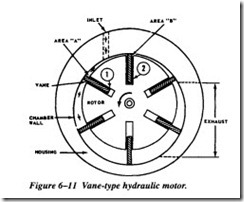
A typical vane-type motor is shown in Figure 6-11. This particular motor provides rotation in only one direction. The rotating element is a slotted rotor, which is mounted on a drive shaft. Each slot of the rotor is fitted with a free-sliding rectangular vane. The rotor and vanes are enclosed in the housing. The inner surface of the housing is offset from the drive shaft axis. When the rotor is in motion, the vanes tend to slide outward due to centrifugal force. The shape of the rotor housing limits the distance the vanes slide.
This motor operates on the principle of differential areas. When pressurized fluid is directed into the inlet port, its pressure is exerted equally in all directions. Since area A is greater than area B, the rotor will tum counterclockwise. Each vane in tum assumes the number 1 and number 2 positions, and the rotor turns continuously. The potential energy of the hydraulic fluid is thus converted into kinetic energy in the form
of rotary motion and force. Many vane-type motors are capable of providing rotation in either direction. The two ports may be alternately used as inlet and outlet.
Piston- Type Motors
Piston-type motors are the most commonly used in hydraulic systems. They are basi cally the same as hydraulic pumps, except they are used to convert hydraulic energy into mechanical (rotary) energy. See Figure 6-12.
The most commonly used hydraulic motor is the fixed-displacement piston type. Some equipment uses a variable-displacement motor where very wide speed ranges are desired. Although directional control valves control some piston-type motors, they are often used in combination with variable-displacement pumps. This pump-motor combination is used to provide a transfer of power between a driving element and a driven element. Some applications for which hydraulic transmissions may be used are speed or constant-torque drives. The advantages of hydraulic transmission of power over mechanical transmission of power are as follows:
1. Quick, easy speed adjustments over a wide range, while the power source is operating at a constant, more efficient speed
2. Rapid, smooth acceleration or deceleration
3. Control over maximum torque and power
4. Smoother reversal of motion

