Actuators
Types of actuator
Compressed air can be used to move, clamp or vibrate some sort of output device. Pneumatic cylinders are the most commonly found actuators, the construction of which is considered in the next chapter. In this chapter some of the other mechanisms are discussed.
Diaphragm cylinders or thrusters
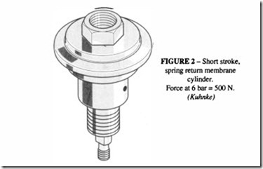
A diaphragm cylinder is a large diameter short stroke cylinder fitted with a diaphragm rather than a piston; it is usually catalogued as a thruster. The construction takes the form of a pair of shallow convex housings, with a diaphragm sandwiched between them and a piston rod attached to the diaphragm. They are usually of a single-rod type, either single acting with spring return or double acting.
They are capable of generating high forces with short strokes, which is what is required for component clamping. The thrust force is equal to the product of the diaphragm area and the pressure. The stroke is limited to about one-third of the diameter, within the flexibility of the diaphragm element.
The thruster body can be made from aluminium castings or steel pressings, clamped or
bolted together as in Figures 1 and 2. The diaphragm is made of neoprene or fabric reinforced nitrile rubber.
The cross-section of the these diaphragm thrusters may be round or assume any other
odless cylinders
For long strokes, the conventional rod-type cylinder has severe space limitations: it has an overall length when extended of twice the stroke plus the length of the end caps; the cylinder rod when extended can flex, resulting in excess wear on the seals and bearings.
Drive Carriage Pulley Wheel
The first attempt to overcome these problems was a cable cylinder. This consists of a piston sliding in the cyIinder barrel attached to a steel cable instead of a piston rod. Pulley wheels are mounted on the cylinder ends and the drive carriage is attached to the cable. This results in a cyIinder with an overall length little more than the stroke (Figure 4). It is possible with some ingenuity to imagine applications where the cable can go round corners and where a rotary drive can be taken from one of the pulleys. The drawbacks are the stretch and wear of the cable which necessitates continual lubrication, adjustment and maintenance; the carriage requires its own supports which can make for a bulky construction.
A band cylinder is similar to a cable cylinder, except that the cable is replaced by a stainless steel band. This is more compact but still suffers the same problems of stretch and need for maintenance.
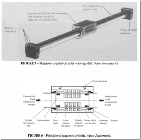
A magnetic cy Iinder is intended to overcome some of these difficulties (Figures 5 and 6). In this design the piston contains a series of permanent magnets operating in a non magnetic, stainless steel tube; a carriage is mounted on the outside of the tube and houses a second set of magnets creating a magnetic coupling between the rod and carriage. This is satisfactory for light, slow moving loads, but the carriage tends to separate under high inertial loads, and the positional register is lost. For slow moving loads, this turns into an advantage because when magnetic break-away occurs, addition mechanical protection is given to the machinery; coupling is only restored when piston and carriage come back into
alignment. Additional guidance may also be required, particularly if there is a tendency for the load to rotate. These cylinders are used for special purposes, where a compact design is important and for such applications as door opening and material handling.
Modern rodless cylinders are based on the band principle, but instead of a continuous band running over pulleys, there is only one pair of bands running from one end cap to the other and connected to the carriage through a slot in the wall of the cylinder. The slot is sealed by the bands made of stainless steel or elastomer. Figure 7 illustrates the construction. The stroke length is little less than the overall length of the cylinder.
The cylinder is made of aluminium extrusion. The slot in cylinder reduces its torsional rigidity, which has to be compensated by additional material in the cross section which can be of a complex form. The piston is also made of aluminium, rigidly coupled to the external carriage.
Despite the apparent complexity, these rodless cylinders work very well and are of use where space is at a premium. The absence of a piston rod means that the whole of the piston area is available for pressure in each direction. The carriage can be supported on guide rods, as shown in Figure 7, or more usually in the body of the cylinder, and requires no additional support A further ingenious development of the rodless cylinder uses a compound cylinder with two bores each with their own carriage. The two carriages move in opposite directions along the length of the cylinder. Ifone carriage is now taken as a fixed point, it can be seen that the other carriage will move almost twice the length of the cylinder (Figure 8). This design incorporates a toothed band to obtain the extended motion.
Rotary actuators
To convert pneumatic pressure into a torque, various devices are available. Continuous rotary motion, as in a pneumatic rotation motor, is dealt with in other chapters. The name rotary actuator implies a limited, rather than a continuous, motion with a torque which is calculated on the basis of pressure and area and is maintained as long as the pressure is applied. It is a quasi-static rather than a dynamic device.
Of the several kinds of rotary actuators, the following are found:
• rotation by a linkage attached to the rod end of a cylinder
• rotation by a pair of cylinders acting in opposition
• a vane actuator, similar to a vane motor but of limited angular movement
• rack and pinion, where the rack is operated by a cylinder
• linear movement of a piston acting on an angled surface, producing limited rotation of a shaft
• rotary indexing tables with a pawl and ratchet mechanism
• linear/rotary devices with a cam track on the piston of the cylinder.
Vane actuators
A vane actuator can have one or two vanes as illustrated diagrammatically in Figure 9, which also shows the range of sizes. The single vane type consists of a vaned shaft with
seal, a shoe (stop) and two barrels. If air enters through port A, it pushes the vane, turns the shaft and generates a clockwise torque. The air in the opposite chamber is discharged through port B, until the vane strikes the shoe and stops. Ifair enters through port Ban anti clockwise torque is generated. The possible total angular movement for a single vane is about 270°. The total angular movement is adjusted by means of the stops.
A double vane type has two vanes, two shoes and two barrels. It is capable of generating approximately twice the torque of the single vane, but the angle of rotation is limited to about 90°. This particular model is available in a range of sizes which at 10 bar pressure can produce a torque of up to 200 Nm for a single vane and 400 Nm for a double vane.
Rack and pinion type actuators
There are several designs available, operated by a single acting cyIinder with spring return, a double acting cylinder or twin cylinders. The basic principal is the same in each: the piston rod of a pneumatic cyIinder becomes a rack which rotates the pinion shaft. In a twin cylinder arrangement it is possible to have a three- or four-position actuator according to which ports are pressurised, as shown in Figure 10. The angular rotation is limited in
principal only by the stroke length of the cylinder, but in practice, standard units rarely exceed about 360°. Up to 400 Nm is possible with this type of design.
Inclined plane devices
In these the linear movement of two pistons produces via angled surfaces a rotation of the drive shaft (Figure 11). The maximum rotation is about 90°. These are miniature devices with a torque capacity of about 2 Nm.
Combined linear/rotary devices
These are of two kinds: in one the linear and rotary motion are independently controlled; in the other the rotation and linear motion are geometrically related through a cam mechanism.
In the former, the rotation unit and cylinder are built into one body with separate air supply to the two units, as illustrated and described in Figure 12. This range is available to produce a torque of 360 Nm combined with a direct extension force of 4.7 kN.
In the latter, the shape of the cam track has to be chosen to produce exactly the right kind of motion. Two types are shown in Figure 13: linear followed by rotary and rotary followed by linear. Simultaneous or more complex motions may be created for special purposes. These are mainly used for clamping purposes.
Air chocks and grippers
These also are intended for clamping and gripping, often used on the end of a robot arm for manipulating components for machining or processing. A variety of different grippers are available :parallel, angled, radial and multi-point, Figure 14.They may rely solely on the force produced by the air or may incorporate a toggle mechanism to hold the
component even if the pressure drops, Figure 15. The short-stroke pneumatic cylinders, which are at the heart of these grippers, may, as with such cylinders, be either double acting, spring return (spring close or spring open) or spring assist (spring assist open or close). The features of these are shown in Figure 16.
Air bellows
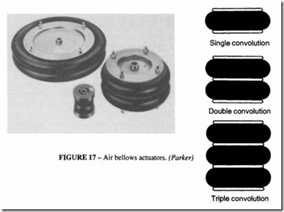
Air bellows are used for short stroke, high thrust applications, available as single, double or triple convolutions, Figure 17. They have no metal reciprocating parts and so can provide virtually frictionless thrust compared with a conventional cylinder. They are single acting only; the return stroke is provide in part by the natural spring action of the bellows, but more usually by the load itself. The simplicity of construction provides an extremely long, maintenance free service life under arduous conditions.
Due to the flexible construction, the mounting of bellows is less critical than with conventional cylinders. They will operate with axial misalignment up to 15° and a maximum axial misalignment of 10 mm. Since the effective diameter reduces as the bellows extend, the force is correspondingly reduced, and this should be taken into account by reference to manufacturers’ literature. The end plates are made of plastic (polyamide) in smaller sizes and steel or aluminium for larger sizes.
In operation, the bellows should not be allowed to bottom out or achieve its maximum


