Trunnion Mount
In this configuration, trunnions or pivot rods are built into either the head or tail block of the cylinder. This type of mounting is used in applications that require movement of the cylinder body as well as that of the cylinder rod. Because both the cylinder body and rod move in this type of mounting configuration, great care must be taken to ensure that sideload and binding are prevented.
Clevis Mount
This type of mounting is similar to a rear-trunnion mount in that it permits the cylin der body to pivot at a point near the tail block. Unlike the trunnion, the clevis mount ing arrangement cannot control the linear movement of the cylinder body. The looseness between the rear clevis and its mating mount and pin permits more uncon trolled side movement than in the trunnion mount.
RACK-AND-PINION, PISTON-TYPE ROTARY ACTUATOR
The rack-and-pinion-type actuators, also referred to as limited rotation cylinders, of the single or multiple bidirectional type are used for turning, positioning, steering,
opening, closing, swinging, or any other mechanical function involving restricted rotation.
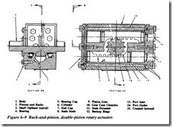
Figure 6-9 shows a typical rack-and-pinion, double-piston actuator. The actuator con sists of a body and two reciprocating pistons with an integral rack for rotating the shaft mounted in roller or journal bearings. The shaft and bearings are located in a central position and are enclosed with a bearing cap. The pistons, one on each side of the rack, are enclosed in cylinders machined or sleeved into the body. The body is enclosed with end caps and static seals to prevent external leakage of pressurized fluid.
In addition to its versatility, the cylinder-type actuator is probably the most trouble free component of fluid power systems. However, it is very important that the cylin der, mechanical linkage, and actuating unit be correctly aligned. Any misalignment will cause excessive wear of the piston, piston rod, and seals. Also, proper adjustment between the piston rod and the actuating unit must be maintained.
HYDRAULIC MOTORS
A fluid power motor is a device that converts fluid power energy into rotary motion and force. The function of a motor is opposite that of a pump. However, the design and operation of fluid power motors are very similar to those of pumps. Therefore, a thorough knowledge of pumps will help you understand the operation of fluid power motors.
Motors have many uses in fluid power systems. In hydraulic power drives, pumps and motors are combined with suitable lines and valves to form hydraulic transmissions. The pump, commonly referred to as the A-end, is driven by some outside source such as an electric motor. The pump delivers pressurized fluid to the hydraulic motor, referred to as the B-end. The hydraulic motor is actuated by this flow and through mechanical linkage conveys rotary motion and force to do work.
Fluid motors may be either fixed or variable displacement. Fixed-displacement motors provide constant torque and variable speed. Controlling the amount of input flow varies the speed. Variable-displacement motors are constructed so that the work ing relationship of the internal parts can be varied to change displacement. The major ity of the motors used in fluid power systems are the fixed-displacement type.
Although most fluid power motors are capable of providing rotary motion in either direction, some applications require rotation in only one direction. In these applica tions, one port of the motor is connected to the system pressure line and the other port to the return line. The flow of fluid to the motor is controlled by a flow control valve, by a two-way directional control valve, or by starting and stopping the power supply. Varying the rate of fluid flow to the motor may control the speed of the motor.
In most fluid power systems, the motor is required to provide actuating power in either direction. In these applications, the ports are referred to as working ports, alter nating as inlet and outlet ports. Either a four-way directional control valve or a vari able-displacement pump usually controls the flow to the motor.
Fluid motors are usually classified according to the type of internal element, which is directly actuated by the pressurized flow. The most common types of elements are gears, vanes, and pistons. All three of these types are adaptable for hydraulic systems, but only the vane type is used on pneumatic systems.
