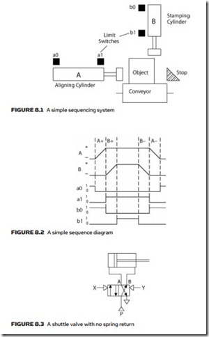
Many industrial processes such as packaging lines consist of pneumatic actuators which follow a predetermined sequence of operations. These sequences can be considered as a series of steps, each step resulting in the operation of pneumatic solenoids. Progression between steps is controlled by sensors on the controlled plant, e.g. photo-cells, stroke limit switches, timers, etc. A typical simple sequence is shown in Figure 8.1, where a product is delivered on a conveyor, moved to the correct position by a horizontal cylinder then stamped by a vertical cylinder.
Associated with these actuators is a series of sensors: a photocell, or similar device, to say a product is present and positional limits to sense the end of stroke for each cylinder.
To aid the design and to assist fault finding it is usual to draw a sequence diagram showing the interaction between the sensors and actuators. Figure 8.1 could be represented by Figure 8.2 where A+ denotes cylinder A extending and A– denotes cylinder A retracting.
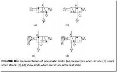
Sequence systems are built around two-position pneumatic shuttle valves. It is important to note that these have no spring return and hold position when the operating signals are removed. A typical example is shown in Figure 8.3. If pneumatic pressure is applied to port X the spool shifts to the right, extending the cylinder. This condition will be held even if the signal is removed from port X. If a signal is now applied to port Y the spool will shift to the left and the cylinder will retract. Again this condition will be held even if the signal is removed from port Y. The valve can be considered to be a memory device with its state being an indication of which signal was last applied. Obviously signals should not be applied to opposing sides of the valve at the same time.
Pneumatic limit switches
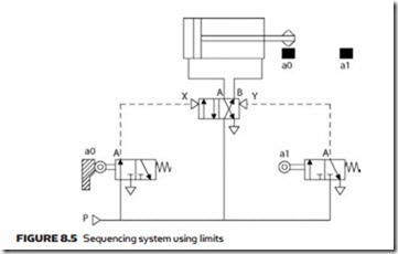
Sequences are driven by limit switches which pass, or block or vent pneumatic pressure. On circuit diagrams limit switches are normally shown in the rest (normally unstruck) state. Figure 8.4a thus vents when unstruck and passes pres- sure when struck. Figure 8.4b passes pressure when unstruck and vents when
If a limit is struck in the rest state (for example, the back-retracted state for a cylinder) it is represented by Figure 8.4c or d. Note the different spool positions between the two sets of symbols a,b and c,d.
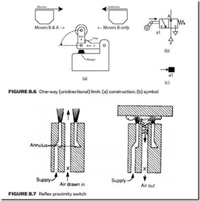
The position of limits is normally shown on a circuit diagram by filled black squares. A simple example of a pneumatic sequencing system is illustrated in Figure 8.5, where the cylinder oscillates continuously between two striker-op-
erated limit switches a0 and a1. The two limits shift the spool of the valve to extend and retract the cylinder.
In some circuits, as we shall see later, it is required to only get a signal from a limit switch when it is struck in a certain direction. These are known as one-way or unidirectional or pulsed limits. A typical construction is shown in Figure 8.6a. The limit has two linked arms A and B. Arm A actually controls the pneumatic signals. Arm B is spring loaded into the vertical position but can move over a 90° arc to the left. If the striker moves from right to left it will only fold down arm B and not operate the limit. If the striker moves from left to right arm B cannot fold down, pushing arm A down and operating the limit. The limit can thus be described as effective from left to right. One-way limits have the symbol in Figure 8.6b and are shown on circuit diagrams with an arrow showing the effective direction.
Pneumatic proximity sensors can also be used. The reflex sensor of Figure 8.7 uses an annular nozzle jet of air, the action of which removes air from the center bore to give a light vacuum at the signal output X. If an object is placed in front of the sensor, flow is restricted and a significant pressure rise is seen at X. Another example is the interruptible jet sensor shown in Figure 8.8, which is simple in operation but uses more air. A typical application could be sensing the presence of a drill bit to indicate ‘drill complete’ in a pneumatically con- trolled machine tool. With no object present, the jet produces a pressure rise at signal output X. An object blocking this flow causes X to fall to atmospheric pressure.
With both of these sensors, air consumption can be a problem. To reduce air usage, low pressure and low flow rates are used. Both of these result in a low-
pressure output signal which requires pressure amplification or low-pressure pilot valves before it can be used to control full pressure lines.
