Pneumatic Piping, Hoses and connections
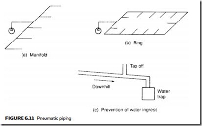
The various end devices in a pneumatic system are linked to the air receiver by pipes, tubes or hoses. In many schemes the air supply is installed as a fixed service similar, in principle, to an electrical ring main, allowing future devices to be added as required. Generally, distribution is arranged as a manifold (as in Figure 6.11a) or as a ring main (as in Figure 6.11b). With strategically placed isolation valves, a ring main has the advantage that parts of the ring can be isolated for maintenance, modification or repair without affecting the rest of the system.
Pneumatic systems are vulnerable to moisture and, to provide drainage, the piping should be installed with a slope of about 1% (1 in 100) down from the res-
ervoir. A water trap fitted at the lowest point of the system allows condensation to be run off, and all tapoffs are taken from the top of the pipe (Figure 6.11c) to prevent water collecting in branch lines.
The pipe sizing should be chosen to keep the pressure reasonably constant over the whole system. The pressure drop is dependent on maximum flow, working pressure, length of line, fittings in the line (e.g. elbows, T-pieces, valves) and the allowable pressure drop. The aim should be to keep air flow non-turbulent (laminar or streamline flow). Pipe suppliers provide tables or nomographs linking pressure drops to pipe length and different pipe diameters. Pipe fittings are generally specified in terms of an equivalent length of standard pipe (a 90 mm elbow, for example, is equivalent in terms of pressure drop to 1 meter of a 90 mm pipe). If an intermittent large load causes local pressure drops, installation of an additional air receiver by the load can reduce its effect on the rest of the system. The local receiver is serving a similar role to a smoothing capacitor in an electronic power supply, or an accumulator in a hydraulic circuit.
If a pneumatic system is installed as a plant service (rather than for a specific well-defined purpose) pipe sizing should always be chosen conservatively to allow for future developments. Doubling a pipe diameter gives four times the cross-sectional area, and pressure drops lowered by a factor of at least ten. Retrofitting larger size piping is far more expensive than installing original piping with substantial allowance for growth.
Black steel piping is primarily used for main pipe runs, with elbow connections where bends are needed (piping, unlike tubing, cannot be bent). Tubing, manufactured to a better finish and more accurate inside and outside diameters from drawn or extruded flexible metals such as brass, copper or aluminum, is used for smaller-diameter lines. As a very rough rule, tubing is used below 25 mm and piping above 50 mm – diameters in between are determined by the application. A main advantage of tubing is that swept angles and corners can be formed with bending machines to give simpler and leak-free installations, and minimizing the pressure drops associated with fittings.
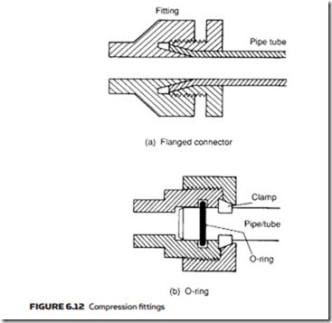
Connections can be made by welding, threaded connections, flanges or compression tube connectors. (Examples of compression fittings are illustrated in Figure 6.12.)
Welded connections are leak-free and robust, and are the prime choice for fixed main distribution pipe lines. Welding does, however, cause scale to be deposited inside the pipe, which must be removed before use.
Threaded pipe connections must obviously have male threads on the pipes. Industry suffers from a lack of consistency in many areas, and not least of these is in standards for screw threads. In pneumatics and hydraulics piping the following pipe fittings may be encountered: American National Pipe Thread (NPT); British Standard Pipe Thread (BSP); Metric Pipe Thread (M10 to M45); Unified Pipe Thread (UNF). Of these NPT and BSP are the commonest.
The choice between these is determined by the standards already chosen for a user’s site. Taper threads are cone-shaped and form a seal between the male and
female parts as they tighten, with assistance from a jointing compound or plastic tapes. Parallel threads are cheaper, but need an O-ring to provide the seal.
A pipe run can be subject to shock loads from pressure changes inside the pipe, and there can also be accidental outside impacts. Piping must therefore be securely mounted and protected where there is a danger from accidental dam- age. In-line fittings such as valves, filters and treatment units should have their own mounting and not rely on piping on either side for support.
At the relatively low pressure of pneumatic systems (typically 5–10 bar), most common piping has a more than adequate safety margin. Pipe strength should, however, be checked – as a burst air line will scatter shrapnel-like fragments at high speed.
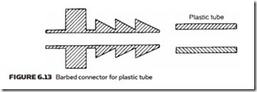
Plastic tubing is used for low-pressure (around 6 bar) lines where flexibility is needed. One advantage of plastic tubing is the availability of multiple colors allowing easy tracing of pipe runs around a machine. Connections are usually made with barbed push-on connectors, illustrated in Figure 6.13. or by quick- release push-in, push-out connectors. Care should be taken when quick-release couplings are used because a volume of compressed air may be trapped down- stream of the coupling and released explosively when the pipe is open ended.
Where flexibility is needed at higher pressure, hosing can be used. Pneumatic hoses are constructed with three concentric layers: an inner tube made of
synthetic rubber surrounded by a reinforcement material such as metal braiding. A plastic outer layer is then used to protect the hosing from abrasion.
Hose fittings need care in use, as they must clamp tightly onto the hose, but not so tightly as to cut through the reinforcement. Quick-disconnect couplings are used where hoses are to be attached and disconnected without the need of shut-off valves. These contain a spring-loaded poppet which closes the outlet when the hose is removed. There is always a brief blast of air as the connection is made or broken, which can eject any dirt around the connector at high speed. Extreme care must therefore be taken when using quick-disconnect couplings.


