Positive displacement pumps
Positive displacement pumps can be classified into two main groups: rotary and reciprocating.
Rotary pumps typically work at pressures up to 25 bar. These pumps transfer liquid from suction to discharge through the action of rotating rotors, screws, lobes, gears, rollers, etc. which operate within a rigid casing. Rotary pumps do not normally require non-return or check valves, in order to function.
Reciprocating pumps typically work at pressures up to 500 bar. These pumps discharge liquid by changing the internal volume. Reciprocating pumps normally require non-return or check valves fitted to suction and/or discharge, these are usually integral with the pump construction.
Flow rates of PO pumps are in general directly proportional to speed, making them ideally suited to flow adjustment by means of variable speed.
Rotary positive displacement pumps
Flow rate, pressure and speed
The relationship between flow rate, pressure and speed varies according to pump type and viscosity of pumped fluid. For pumps having a fall off in flow rate with increasing pressure, the flow rate discrepancy is referred to as ‘slip flow’, see Figure 4.11. Rotary PO pumps with minimal slip flow can create very high, possibly dangerous pressures if the system is incorrectly selected or a valve on the discharge is closed or even nearly closed. This occurs because the characteristic of this type of pump is constant flow, which causes the pressure to rise to force the flow through the tightest restriction. If the discharge flow can be reduced to zero, safely, by increasing the pressure from P1 to P2 then this is referred to as ‘dead
Considering the effect of speed change on volumetric efficiency, for the particular example shown in Figure 4.12, it can be demonstrated that by reducing speed from n1 to n2 whilst maintaining a constant pressure P2 , volumetric efficiency is reduced from 70% to 50%. Volumetric efficiency is the ratio of volume delivered to displaced volume. When there is no slip, the volumetric efficiency is 100% and the flow rate versus speed relation ship follows the no-slip line.
Unlike rotodynamic pumps, changing system resistance i.e. by closing a valve cannot control the flow rate of most PD pumps. This simple method is both ineffective and potentially unsafe as these pumps have the potential to generate very high pressure, under such circumstances.
Suction performance
In a similar way to that described in 4.2.1.3, a PD pump needs the incoming liquid to have a pressure margin above liquid vapour pressure to prevent cavitation within the suction passages or pumping chamber. For a PD rotary pump, the required pressure at the inlet is referred to as NPSHR (net positive suction head required). NPSHR characteristics are determined by the geometry and construction of the design, with little ability to change without major modifications.
The cavities on a positive displacement pump open and close as the pump operates and the liquid must flow quickly enough at the pump suction to fill the cavities completely with liquid. If the cavities do not fill with liquid, there will be a void, and apparent cavitation, resulting in a loss of both flow and pressure performance. If the speed is increased, this filling process becomes more problematical, limiting the maximum speed. With viscous liquids, the effect is more severe.
Speed and torque
Rotary PD pumps have a constant torque characteristic in contrast to that of rotodynamic pumps whose torque required is proportional to speed squared.
Although the torque required to drive a PD pump, in general, is directly proportional to differential pressure and independent of speed, the torque required to drive the pump across a speed range may vary, depending on the pump operating principle, materials of construction, running clearances and the viscous behaviour of the liquid.
Some rotary PD pump types have a high starting torque. This may result from start-up friction where the pumped liquid is required to lubricate moving mechanical components, or may occur if the pump employs an elastomeric pumping element that displays hysteresis. Starting torque can be significantly more than the normal running torque and can be a major factor in sizing a drive (see Section 8.3.1). Advice should be sought from the pump manufacturer for any application beyond published data.
Speed and power absorbed
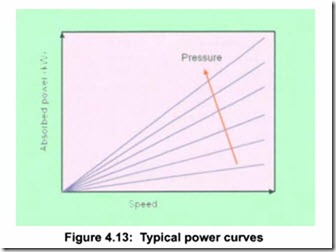
Typical power absorbed curves vary linearly with speed and pressure; examples are shown in Figure 4.13. Viscosity is assumed constant in the
illustration; an increase in viscosity will increase power absorbed. Again advice should be sought from the pump manufacturer.
Reciprocating positive displacement pumps
Principles
Reciprocating pumps can generally be classified as having a piston, plunger or diaphragm, displacing a discrete volume of liquid between an inlet valve and a discharge valve.
The rotary motion of the driver, such as an electric motor, is converted to the reciprocating motion by either a crankshaft, camshaft or swash plate.
The pump can have a number of pumping elements, e.g. plungers, generally between 1 and 7.
The simplest form is a single plunger usually referred to as a single cylinder or simplex pump.
For reciprocating positive displacement pumps, inlet requirements are better expressed by Net Positive Inlet Pressure (NPIP) rather than NPSH.
Simplex pump There are many more components in such a pump compared to those found in a rotodynamic pump. e.g. crankcase and cover, crankshaft with bearings and seals, connecting-rod, plunger rod, plunger, seals, and a pump cylinder head with inlet and discharge valve assemblies.
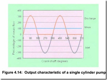
Figure 4.14 shows the plunger displacement with crankshaft rotation. From 0 degrees, bottom dead centre, to 180 degrees, top dead centre, flow is taking place. The area under the curve gives the total volume displaced. TheY-axis also represents how flow rate varies with crankshaft rotation. Between 180 degrees and 360 degrees, filling of the cylinder is taking place but there is no discharge flow. The output is a series of sinusoidal humps.
In practice there will be a short delay to the start of the ‘hump’ as clearance is taken up between the connecting rod and the crankshaft; also the discharge valve will be delayed in opening as the pressure increases in the cylinder and the valve inertia is overcome. There will be a similar effect at the end of the ‘hump’ as mechanical clearance is taken up, the pressure difference across the inlet valve is generated and the inlet valve inertia is overcome.
The flow rate Q is a function of time Q(t) and rises from 0% to 315% of the mean flow in a quarter of the revolution. In the next quarter revolution, pumping continues, but the flow rate falls from 315% of the mean to 0%.
In the second half of the revolution nothing is being pumped as during this time the cylinder re-fills. Pressure will generally also vary with time because the flow rate is so uneven.
Even if the pump is delivering to a constant pressure, the torque requirement from the driver has the same large fluctuation of up to 315% of the mean and follows the same profile as the flow rate in Figure 4.14.
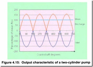
Duplex pump Adding another set of parts: con-rod, plunger rod, plunger and seals, inlet and discharge valve assemblies, creates a two cylinder or duplex pump. The second plunger is set 180 degrees out of phase with the first. This gives a degree of improvement over a simplex pump, but there is still a wide variation in the flow rate, and hence the torque, see Figure 4.15. The fluctuation still goes from 0% but only reaches 157% of the mean. The frequency is 2 x (r/min)/60 Hz.
Triplex pump Adding a third set of parts makes a dramatic difference, because for two thirds of the stroke there are two plungers discharging at the same time and for the remaining one third one plunger is near to maximum output. The three outputs add together to give a smoother waveform. This is shown in Figure 4.16. Although this is theoretical, a well-designed pumping system will exhibit this waveform albeit being somewhat less smooth.
The flow and hence torque variation is from 90% to 104% of the mean, a total of 14%.
Adding further sets of parts, effects a more limited improvement, which only becomes cost effective for special duties.


