Fault-finding instruments
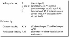
Electrical fault-finding is generally based on measurements of voltage, current or (less often) resistance at critical points in the circuit. Of these, voltage is easier to measure than current unless ammeters or shunts have been built into the circuit, and resistance measurement usually requires the circuit to be powered-down and the device under test disconnected to avoid sneak paths. An electronic circuit is given in Figure 8.2. This converts a voltage input Vi to a current signal I, where I = V/R. Such a circuit is commonly used to transmit an instrumentation signal through a noisy environ ment. A typical checking procedure could be:
In pneumatic or hydraulic systems, pressure measurement is equivalent to electrical voltage measurement, while flow measurement is equivalent to current measurement. There is no direct simple measurement equivalent to electrical resistance. Pressure tests and (to a lesser extent) flow tests thus form the bases of fault finding in pneumatic or hydraulic systems.
There is however, a major difference in the ease of access. Electrical systems abound with potential test points; a voltage probe can be placed on practically any terminal or any component, and (with a little more trouble) a circuit can be broken to allow current measurements to be made.
In fluid systems, oil or gas is contained in pipes or hoses, and measurements can only be made at test points which have been built-in as part of the original design. Test points can be plumbed in on an ad hoc basis but this carries the dangers of introducing dirt from cutting or welding, and in hydraulic systems any air intro duced will need to be bled out. The designer should, therefore, care fully consider how faults in the system can be located, and provide the necessary test points as part of the initial design.
By far the most common technique is a built-in rotary pressure select switch, as shown in Figure 8.3, which allows pressure from various strategic locations to be read centrally. An alternative tech nique uses quick-release connections, allowing a portable pressure meter to be carried around the system and plugged in where required.
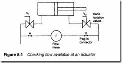
Flow measurement is more difficult, as the basic flow transducer needs to be built-in. Portable flow meters can be used, as shown in Figure 8.4, where the flow available for a cylinder is checked by closing hand valves V 1 and V2 while connecting a flow meter between quick-release connections A and B.
The UCC System 22 is an invaluable three in one ‘plumbed-in’ test instrument which provides measurement of pressure, flow and temperature at the installed point with a plug in test meter. The inclusion of such a device should be provided immediately after every pump (but before the first relief valve) to allow pump delivery to be checked and at crucial points such as the pressure lines to a critical cylinder or motor. Remember, with hydraulics and pneu matics the test points have to be designed in.
An indicator in the plug of a solenoid valve will show voltage is arriving at the solenoid (see Figure 8.9) but this is not a fool proof indication that the solenoid itself is operating. The coil may, for example, be open circuit or there is a loose connection inside the plug. RS components sell a very cheap and useful solenoid tester (part number 214-338), which illuminates when held in a strong magnetic field. About the size of a fountain pen it can be touched onto the body of a solenoid to see if the solenoid really is being energized.


