Flow regulated by throttling
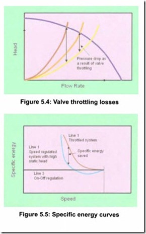
When the flow is regulated using a throttling valve , the system curve is changed. The duty point moves to the left on the pump curve, when the flow is throttled , see Figure 5.4. The vertical lines in Figure 5.4 represent the throttling loss in the valve . The specific energy can be calculated for each operating point by dividing the input power to the motor by the flow rate. E5 usually increases rapidly as the flow is reduced, typically like the curve 1 in Figure 5.5.
Compared to regulation by throttling, a variable speed drive always saves energy. Line 3 in Figure 5.5 represents the specific energy for an on-off regulated pump.
The specific energy for a speed regulated pump system can be higher than that for an on-off regulated system especially at low flow rates , but will be lower and certainly save energy compared with a throttled system .
Parallel pumps common header
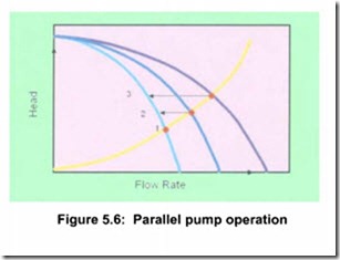
It is important to understand that parallel pumps operating with VSDs and discharging into a common header exhibit the same behavior as previously described when operating a pump against a static head, whether or not static head is present. The first pump discharging to the header pressurizes the header. The second and subsequent pumps that come on line must then pump into a pressurized header. The more pumps that are running the higher the pressure in the header, which limits the chances of saving energy by using a variable speed drive. See Figure 5.6 for a graphical explanation.
With three pumps running, each pump operates at point 3 in Figure 5.6. Thus, a fourth pump must deliver at least this pressure before it produces any flow. This situation is, therefore, identical to pumping against a static head.
This is relevant to water and wastewater schemes where variable speed pumps running in parallel are growing in popularity. Optimization of the variable speed system is essential and specialist advice should be sought. However, as a common rule all the pumps should run to a similar characteristic, which usually means running identical pumps at identical speed. Similarly it is not recommended to run a fixed speed pump in parallel with a variable speed pump of the same size. The potential problem that can arise, and must be avoided, is that one of the pumps operates at no flow.
System awareness – notes of caution
To understand a pumping system it must be realized that all of its components are interdependent. Sub-optimization at the component level can easily be deceptive.
The true cost of pumping can be calculated by using the information from Figure 5.1 and Equation (8) where Es has to be evaluated for all flow rates. In most instances, pumps are sized to deliver the peak flow rate with some margin upwards. With duration curves looking like the continuous curve in Figure 5.1, it is therefore common that the normal flow rate is around, or less than, 50 percent of the design flow.
If the system curve exhibits a fair amount of static head and the pump is oversized for most of the pumping needs, then problems can occur. It is not uncommon in such systems to find that the cost of pumping is consid erably increased when using a variable speed drive, compared with on-off pumping at full speed. This is generally due to falling pump efficiency at lower flow rates as explained earlier. The fact that the combined efficiency of a variable speed drive-motor package can drop considerably as the load is decreased, does not make the situation better. Thus the allowable speed range becomes restricted both from an operational and economical point of view in such systems. Throttling the flow, however, is still worse!
Conclusions on a VSD within a system
Variable speed drives will give good control of the flow rate. They generally greatly reduce the operating cost in all systems when compared to throttling-valves. In systems with high relative static head, extra care has to be taken when using variable speed drives, to avoid the pitfalls of low pumping efficiency and operation in harmful flow regimes. In systems with little or no static head VSDs will show reduced operational cost over any other method of flow control.

