Diaphragm Accumulators
The diaphragm-type accumulator is constructed in two halves, which are either screwed or bolted together. A synthetic rubber diaphragm is installed between the two halves, making two separate chambers. Two threaded openings exist in the assembled component.
The opening at the top, as shown in Figure 5-4, contains a screen disc, which prevents the diaphragm from extruding through the threaded opening when system pressure is depleted, thus rupturing the diaphragm.
On some designs, a button-type protector fastened to the center of the diaphragm replaces the screen. An air valve for pressurizing the accumulator is located in the gas chamber end of the sphere, and the liquid port to the hydraulic system is located on the opposite end of the sphere. This accumulator operates in a manner similar to the bladder type.
Accumulator Sizing
Most accumulator systems should be designed to operate at a maximum oil pressure of 3,000 psi. This is the rating of most accumulators and will give the maximum effect for the least cost. Also, 3,000 psi is the maximum rating for most hydraulic valves.
A rule of thumb for the nitrogen precharge level is one-half the maximum oil pressure. This is acceptable for most applications. The precharge should be replenished when it falls to one-third the maximum hydraulic oil pressure. On a 3,000-psi hydrau lic system, initial precharge should be 1,500 psi and replenishment level of 1,000 psi. Most applications will tolerate a wide variation in precharge pressure.
Accumulators are catalog-rated by gas volume when all oil is discharged and usually rated in quarts or gallons (i.e., 1 U.S. gallon= 231 cubic inches). The amount of oil that can be stored is approximately half the gas volume. Only a part of the stored oil can be used each cycle because the oil pressure decreases as oil is discharged. The problem in selecting accumulator size is to have sufficient capacity that system pres sure, at the end of the discharge, does not fall below a value that will do the job.
For illustration we are using an application in which accumulator oil will be used on the extension stroke of a cylinder to supplement the oil delivery from a pump, to increase speed. Retraction will be by pump volume alone. A fully charged accumula tor system pressure of 3,000 psi is assumed.
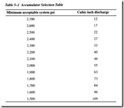
First, select cylinder bore for sufficient force not only at 3,000 psi but also at some selected lower pressure to which it will be allowed to fall during discharge. Next, calculate the number of cubic inches of oil required to fill the cylinder cavity during its extension stroke. Using the time, in seconds, allowed for the full extension stroke, calculate the cubic inches of oil that can be obtained for the pump alone. Subtract the calculated pump volume from the cylinder volume to find the volume of oil required from the accumulator. Use Table 5-l to find how many cubic inches of oil would be supplied from a 1-gallon accumulator before its terminal pressure dropped below the minimum acceptable pressure level. A 5- gallon accumulator would supply five times this volume. Finally, divide this fig ure into the total cubic inches needed for the application. This is the minimum rated gallon size of accumulator capacity. Select at least the next larger standard size for your application.
To solve for oil recovery from any size accumulator, under any system pressure and any precharge level, use the formula
where D is cubic inches of oil discharge; P 1 is precharge pressure in psi; P 2 is system pressure after volume D has been discharged; P 3 is maximum system pressure at full accumulator charge; V1 is catalog-rated gas volume, in cubic inches; and 0.95 is assumed accumulator efficiency.
As oil is pumped into the accumulator, compressing the nitrogen, the nitrogen tem perature increases (Charles’ law). Therefore, the amount of oil stored will not be quite as much as calculated with Boyle’s law unless sufficient time is allowed for the accu mulator to cool to atmospheric temperature. Likewise, when oil is discharged, the expanding nitrogen is cooled. So the discharge volume will not be quite as high as calculated with Boyle’s law. In the table and formula above, an allowance of 5 percent has been included as a safety factor. After making a size calculation from the table, allow enough extra capacity for contingencies.

