Review of pneumatic conveying systems
Introduction
A wide range of different pneumatic conveying systems are available to cater for an equally wide range of different applications. The majority of systems are generally conventional, continuously operating, open systems in a fixed location. To suit the material being conveyed, the application, or the process, however, innovatory, batch operating and closed systems are commonly used, as well as mobile systems.
To add to the complexity of selection, systems can be either positive or negative pressure in operation, or a combination of the two. The combined system is effectively achieved by means of staging, but this is a further possibility in its own right. In this brief review some of the more common systems are presented, and an explanation is provided of the different types to help in the selection process.
Numerous requirements of the conveying system, and conditions imposed by the material to be conveyed, also have to be taken into account as they present a number of important points to consider in the selection process. A checklist is provided, therefore, of possible system requirements, and specific features of bulk particulate materials, as these may ultimately dictate choice.
System types
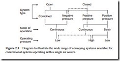
The problem of system selection is illustrated in Figure 2.1. This shows the range of combinations that are possible just for conventional pneumatic conveying systems
with a single air source. Only system types are presented in detail, with positive pressure, vacuum, and combined positive and negative pressure systems considered, in rela- tion to both open and closed systems.
Material fed into the conveying pipeline is only expressed in terms of mode of operation at this point, as feeding devices are considered in detail in Chapters 3 (low pressure) and 4 (high pressure). With a natural limit on operating pressure with vac- uum systems, air requirements are included here in terms of a high or low operating pressure. Air movers are also considered separately in Chapter 6.
Open systems
Where strict environmental control is not necessary, an open system is generally used. Most pneumatic conveying pipeline systems can ensure totally enclosed material con- veying, and so with suitable gas–solid separation and venting, the vast majority of materials can be handled quite safely in open systems. Many potentially combustible materials are conveyed in open systems by incorporating necessary safety features. Air is used for the conveying of most materials. Nitrogen and other gases can be used for particular materials and applications, but because of the added cost of operation closed loop systems are more commonly used in these cases.
Positive pressure systems
Although positive pressure conveying systems discharging to a reception point at atmospheric pressure are probably the most common of all pneumatic conveying sys- tems, the feeding of a material into a pipeline in which there is air at pressure does present a number of problems. A wide range of material feeding devices, however, are available that can be used with this type of system, from verturis and rotary valves to screws and blow tanks, and these are considered in detail in Chapters 3 and 4. A sketch of a typical positive pressure system is given in Figure 2.2.
With the use of diverter valves, multiple delivery to a number of reception points can be arranged very easily with positive pressure systems, as illustrated in Figure 2.2. Although multiple point feeding into a common line can also be arranged, care must be taken, particularly in the case of rotary valve feeding of the pipeline, since air leak- age through a number of such valves can be quite significant in relation to the total air requirements for conveying.
Negative pressure (vacuum) systems
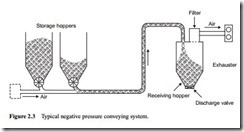
Negative pressure systems are commonly used for drawing materials from multiple sources to a single point. There is little or no pressure difference across the feeding device and so multiple point feeding into a common line presents few problems. As a consequence, the feeding device can be a very much cheaper and simpler item in a negative pressure system than in a positive pressure system. A sketch of a typical sys- tem is given in Figure 2.3.
It will be seen from Figure 2.3 that the receiving hopper and filtration unit both have to operate under vacuum in this system. As a consequence of this there are three further basic differences between the negative and positive pressure conveying sys- tems to be considered:
1. The receiving vessel has to be designed to withstand the appropriate vacuum.
2. The filtration plant has to be larger, as a higher volume of air has to be filtered under vacuum conditions.
3. In continuously operating systems material will need to be withdrawn from the reception vessel, but with it operating under vacuum air may leak across the dis- charge valve. This is effectively a ‘mirror image’ of the problem of feeding material against an adverse pressure gradient reported above for the positive pressure system in Figure 2.2.
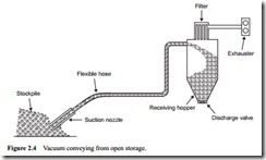
Negative pressure systems are also widely used for drawing materials from open storage and stockpiles, where the top surface of the material is accessible. This is
achieved by means of suction nozzles. Vacuum systems, therefore, can be used most effectively for off-loading ships. They are also particularly useful for cleaning processes, such as the removal of material spillages and dust accumulations. A sketch of a typical system is given in Figure 2.4.
Vacuum systems have the particular advantage that all gas leakage is inward, so that injection of dust into the atmosphere is virtually eliminated. This is particularly important for the handling of toxic and explosive materials. It is not always necessary to employ a closed system with these materials, therefore, provided that adequate safety measures are taken, particularly with regard to exhaust venting.
As a result of the conveying air being drawn through the air mover, it is essential that the exhauster should be protected from the possibility of the failure of one or more of the filter elements in the gas–solids separation system. This can be achieved by incorp- orating a back-up filter. Stand-by filters are rarely employed and so the purpose of the back-up filter is simply to allow sufficient time for the plant to be shut down safely and conveniently so that repairs can be carried out. The back-up filter, therefore, can be a simple device, but the upstream pipeline must be provided with monitoring equipment for detection purposes.


