PNEUMATIC-MECHANICAL SYSTEMS
Almost all pneumatic cylinders operate some kind of mechanical device. The most common type of device is the lever or lever system.
The change in force resulting from a mechanical system is called mechanical advantage. The use of a lever system typically provides an increase or decrease in mechanical advantage. It is very important to realize that the same amount of work is being done regardless of mechanical advantage.
Figure 20-4 shows how a lever can be made to work to our advantage.
The components of a lever system are a lever, lever arm, force, and load. Another impor tant part of the system is the fulcrum. The fulcrum is the point about which the lever rotates. The distance from the fulcrum to the load multiplied by the amount of load will be equal to the distance from the fulcrum to the force multiplied by the amount of force required to move the load. Attaching a cylinder to supply the force and utilizing the proper distances from the fulcrum allows cylinders to move very large loads.
PRESSURE, FORCE, AND AREA
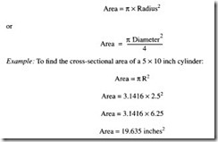
The relationship between pressure, force, and area is one of the most important concepts in pneumatics. It can be used to calculate the forces in the cylinders, tubing, and other pneumatic equipment. The relationship is as follows:
The pressure refers to the actual system pressure in pounds per square inch. Typically this will be the pressure indicated on the manifold gauge and is the gauge pressure (psig). The force developed by the cylinder is a function of the pressure and the area of the cylinder. The force in most cases is the product of the gauge pressure (psig) and the area of the cylinder (inches2).

